CoolPi 4B硬件扩展二:Serial port
-
串口位置
下表罗列了40PIN连接器可以用做UART功能的引脚,目前除了debug串口以外还可以扩展5路独立串口。最大波特率1.5M。IO电平是TTL 3.3V。注意:串口号和实际系统的节点不是一一对应,实际操作需要按照表格对应的设备节点。
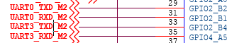
序号 端口定义 描述 IO电平 设备节点 29 UART0_TX_M2 UART0 发送 TTL 3.3V /dev/ttyS6 31 UART0_RX_M2 UART0 接收 TTL 3.3V /dev/ttyS6 33 UART3_TX_M2 UART3 发送 TTL 3.3V /dev/ttyS3 35 UART3_RX_M2 UART3 接收 TTL 3.3V /dev/ttyS3 19 UART4_RX_M2 UART4 接收 TTL 3.3V /dev/ttyS4 23 UART4_TX_M2 UART4 发送 TTL 3.3V /dev/ttyS4 16 UART6_TX_M1 UART6 发送 TTL 3.3V /dev/ttyS2 18 UART6_RX_M1 UART6 接收 TTL 3.3V /dev/ttyS2 24 UART7_RX_M2 UART7 接收 TTL 3.3V /dev/ttyS7 26 UART7_TX_M2 UART7 发送 TTL 3.3V /dev/ttyS7 DTS配置
用户需要使用哪个串口在DTS打开对应节点即可,status = "okay"代表开启,status = "disabled"代表关闭。注意不使用UART功能确保对应节点的status是disabled状态,否则可能会导致其它功能异常。
&uart0 {
	pinctrl-names = "default";
	pinctrl-0 = <&uart0m2_xfer>;
	status = "okay";
};

&uart3 {
	pinctrl-names = "default";
	pinctrl-0 = <&uart3m2_xfer>;
	status = "okay";
};

&uart4 {
	pinctrl-names = "default";
	pinctrl-0 = <&uart4m2_xfer>;
	status = "okay";
};

&uart6 {
	pinctrl-names = "default";
	pinctrl-0 = <&uart6m1_xfer>;
	status = "okay";
};

&uart7 {
	pinctrl-names = "default";
	pinctrl-0 = <&uart7m2_xfer>;
	status = "okay";
};
shell测试命令
功能测试采用回环测试(对应串口的TX RX信号短接)。
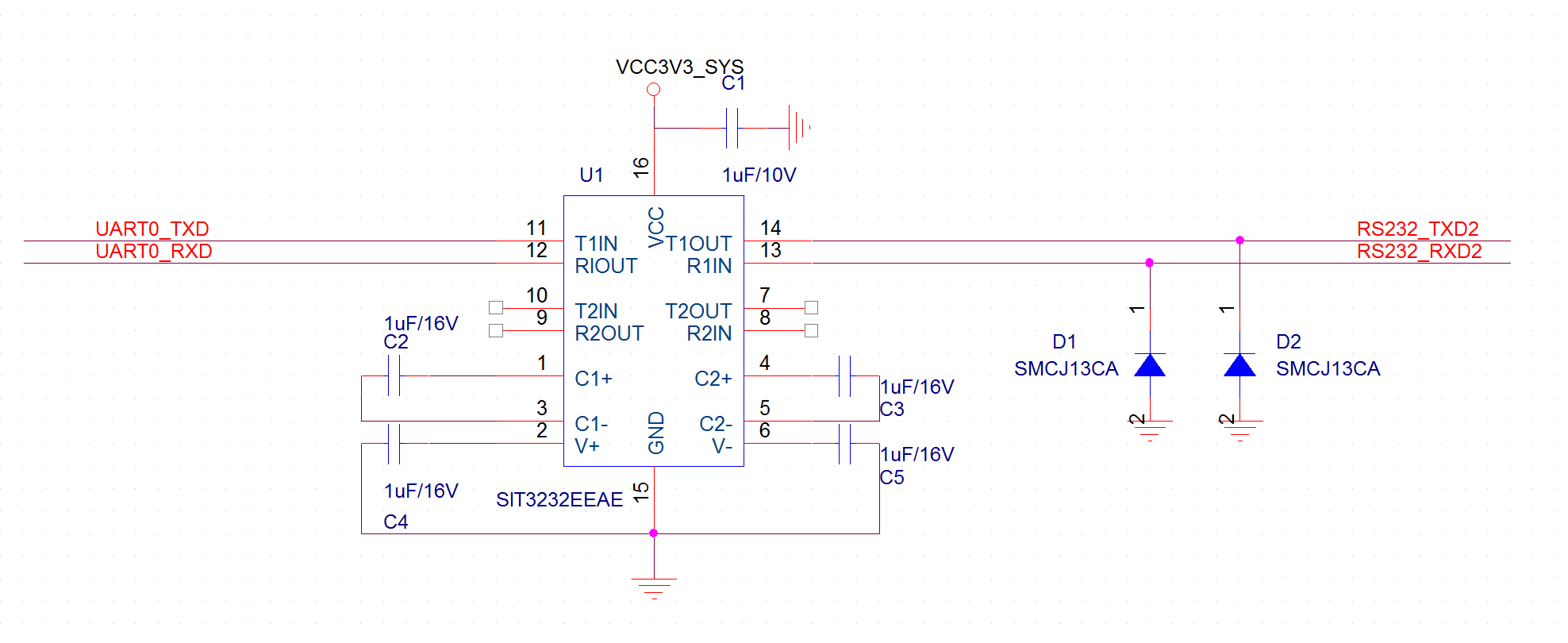
stty -F /dev/ttyS6 raw speed 115200 //配置PIN29 PIN31对应的串口波特率为115200
echo "hello world" > /dev/ttyS6 //发送字符串
cat /dev/ttyS6 //接收字符串
RS232电路
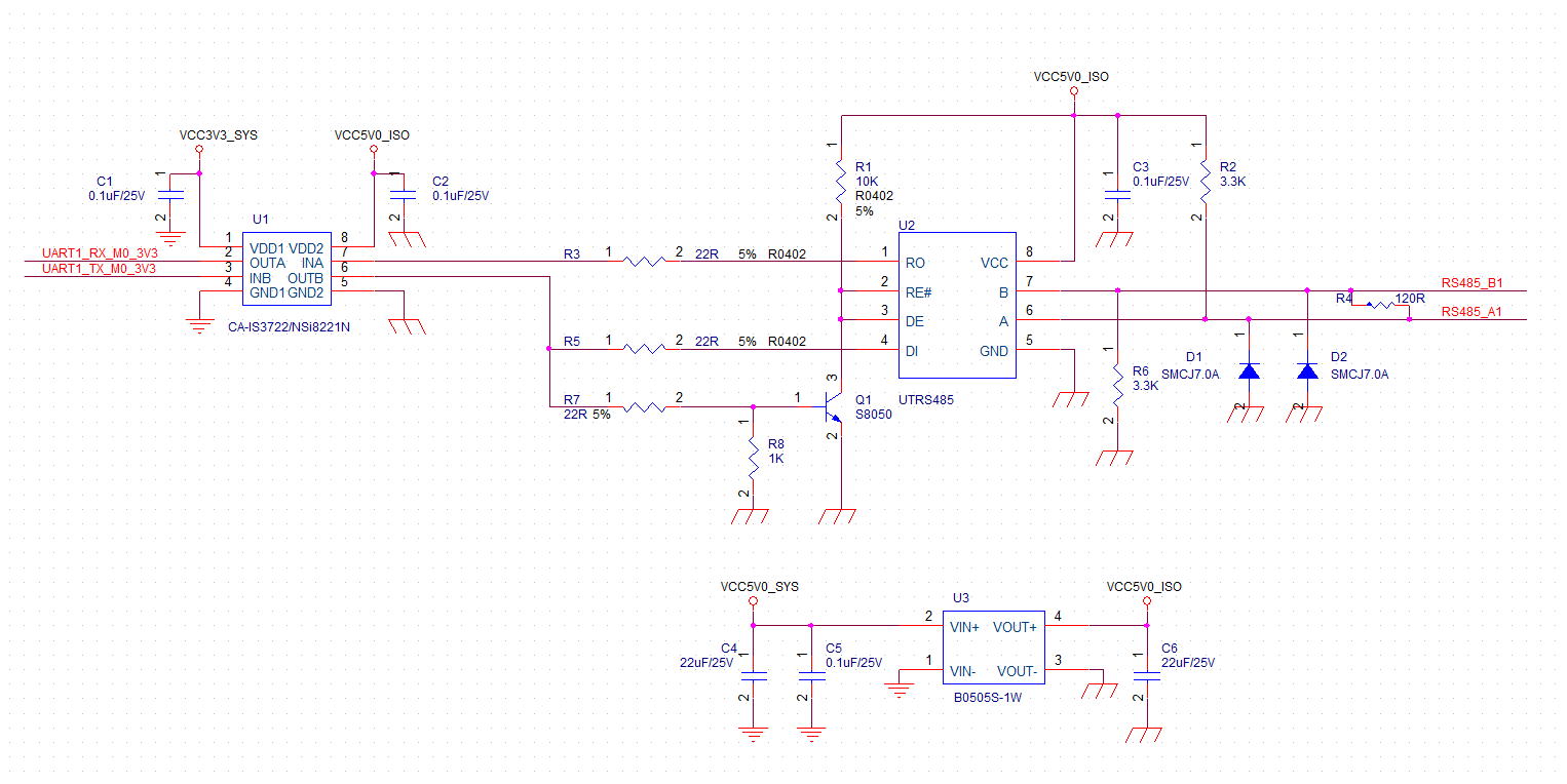
隔离485电路
-
Locked by G george Nov 9, 2022, 4:38 AM
-
Unlocked by G george Nov 9, 2022, 4:56 AM
-
It seems that the DTB file has changed a lot in the 20.04 ubuntu image. I can only find uart3-m1-xfer instead of the needed uart3-m2-xfer in DTS file converted from rk3588s-cp4.dtb. What should I do in order to use uart3 under this circumstance?
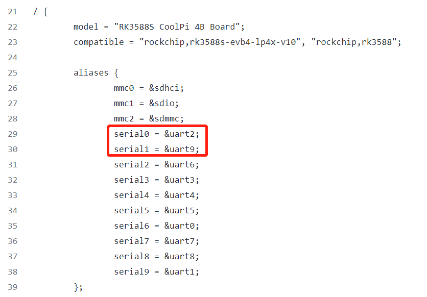
uart2 { uart2m0-xfer { rockchip,pins = <0x00 0x0e 0x0a 0x167 0x00 0x0d 0x0a 0x167>; phandle = <0x136>; }; }; uart3 { uart3m1-xfer { rockchip,pins = <0x03 0x0e 0x0a 0x167 0x03 0x0d 0x0a 0x167>; phandle = <0x137>; }; }; uart4 { uart4m1-xfer { rockchip,pins = <0x03 0x18 0x0a 0x167 0x03 0x19 0x0a 0x167>; phandle = <0x138>; }; }; uart5 { uart5m1-xfer { rockchip,pins = <0x03 0x15 0x0a 0x167 0x03 0x14 0x0a 0x167>; phandle = <0x139>; }; }; -
uart2 node is used for console and uart9 node is used for bluetooth.
-
@大法师 Many thanks for your reply, but unoccupied serial ports accessible from GPIOs include uart3,6. There left only uart6 if uart3 can't be functional. Is it possible to activate uart3-m2-xfer?
- topic:timeago_later,9 months
-
This post is deleted! -
有办法把console关闭吗?使用uart2-ttyS0作为一路普通串口
-
@AugustRobot_Zou
可以,但是比较麻烦,需要改loader uboot kernel,现在扩展口上面串口不够用吗? -
@george 目前是刚好够用的,我以为跟其他串口一样改一下内核设备树就能多一个备用串口,如果太麻烦就算了暂时不用,别引出其他bug了。
-
@AugustRobot_Zou 如果不介意开机启动阶段的一些串口输出,可以直接修改配置参数,把ttyS0当做普通串口使用。
/boot/firmware/extlinux/extlinux.conf
console=ttyS0,115200 改为 console=tty0 -
板上I/O口的对应哪个呀,都没标注出来
-
系统上显示的为0,1,2
-
@阿里
wiki上有原理图和PCB也有标识第一脚位置,数一下就可以确定了。 - topic:timeago_later,5 months
-
请问一下,我这边看完了wiki,我目前理解是,如果从网盘中下载下来的镜像,仅开启了uart2、9、6。其中uart2也就是ttyS0作为debug口。uart9也就是ttyS1和uart6也就是ttyS2作为普通串口。
但是我有如下问题:
- 我没有找到uart9(ttyS1)对应的外部引脚,从电路图上看似乎是用来做蓝牙的串口了?
- 如果我希望不改动debug口的情况下,引脚上有至少两个可用串口,是否我需要重写dts,然后重编内核,再打包镜像?我对bsp不太熟,希望大佬指导一下。
-
@银河铁道
修改DTS配置,然后把编译生成的dtb文件拷贝到boot分区重启即可。 -
@银河铁道 said in CoolPi 4B硬件扩展二:Serial port:
请问一下,我这边看完了wiki,我目前理解是,如果从网盘中下载下来的镜像,仅开启了uart2、9、6。其中uart2也就是ttyS0作为debug口。uart9也就是ttyS1和uart6也就是ttyS2作为普通串口。
但是我有如下问题:
- 我没有找到uart9(ttyS1)对应的外部引脚,从电路图上看似乎是用来做蓝牙的串口了?
- 如果我希望不改动debug口的情况下,引脚上有至少两个可用串口,是否我需要重写dts,然后重编内核,再打包镜像?我对bsp不太熟,希望大佬指导一下。
ttyS1用作蓝牙通信
- topic:timeago_later,4 months
-
@george 请问有相关教程可以参考吗?
-
@大法师 改完之后重启,会生效。但是重新上电就又不行了,还得带电重启一次 请问这可能是怎么造成的呢
-
@santu
重启和重新上电以后运行如下命令发出来ls /dev/ttyS*