G
Best posts made by george
-
RE: 请问coolpi 4b 电源输入功率多大合适,有电流保护吗?posted in Peripheral
@night 机器TYPEC前端电源芯片耐压可以达到28V,极限可以到34V,所以你的适配器规格没有任何问题。
开发板的电源部分一直是我们设计最优先考虑的方向,所以前端第一级电源花了很多功夫,考虑到用户各种各样适配器的规格,最终选择目前国内少数几家真正能做车规级别电源方案的厂家。尽量保证前端电源稳定可靠。
-
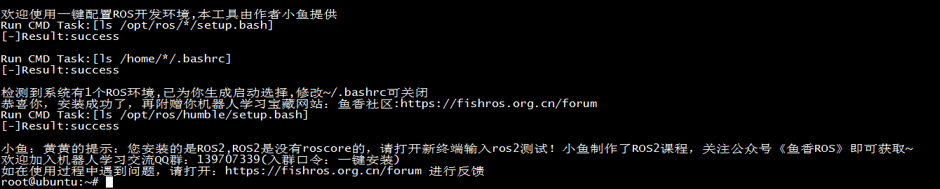
ubuntu22.04一键安装ROS2环境posted in Ubuntu
root登录shell键入如下命令:
root@ubuntu:/# wget http://fishros.com/install -O fishros && bash fishros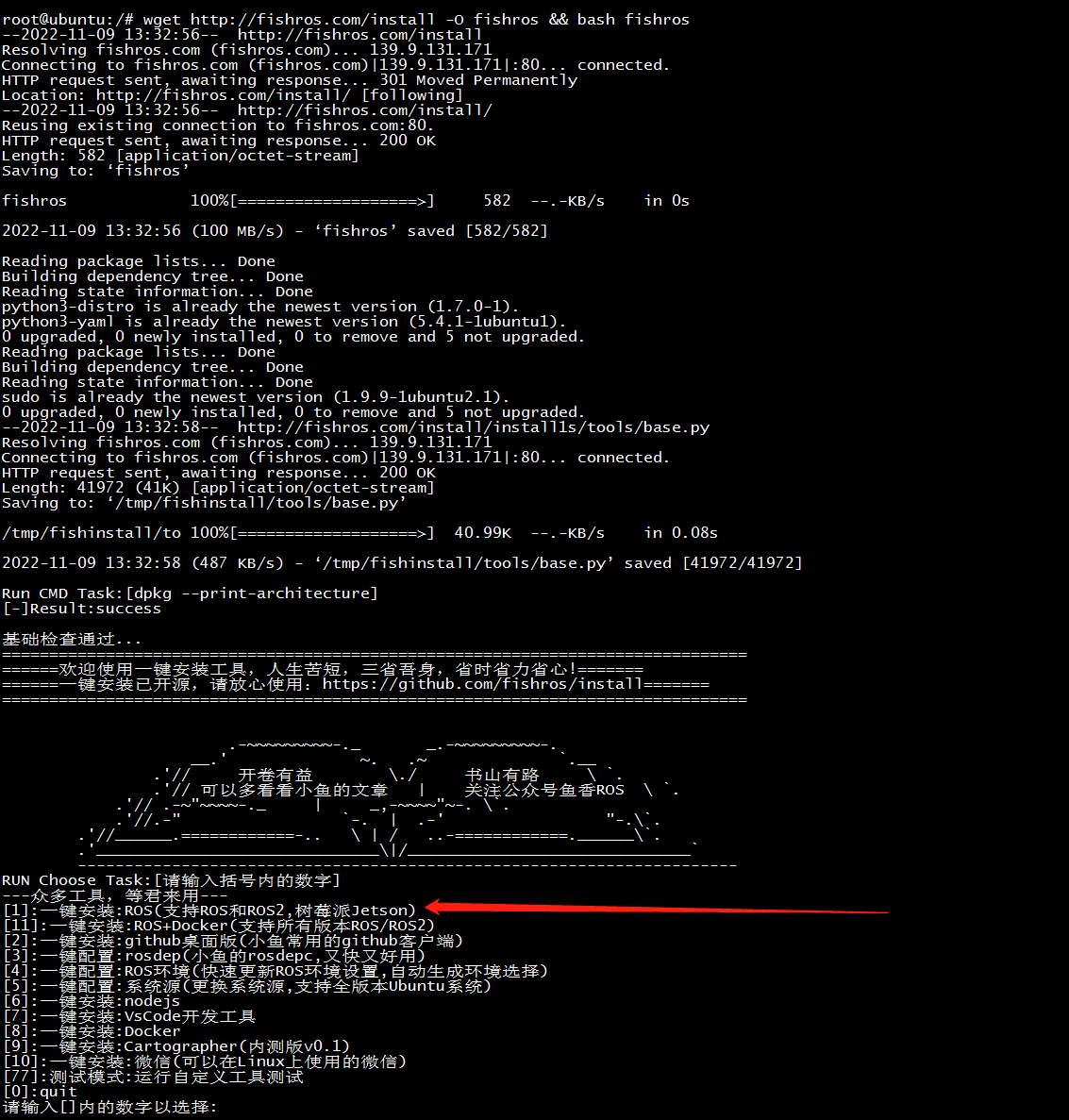
选择更新源速度会大幅度提高
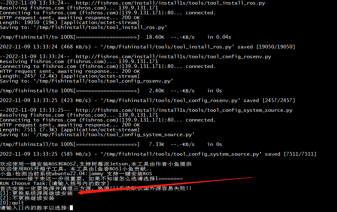
选择humble

选择桌面版

安装成功界面
简单测试:
两个shell终端分别输入下面两条指令$ros2 run demo_nodes_py listener $ros2 run demo_nodes_cpp talker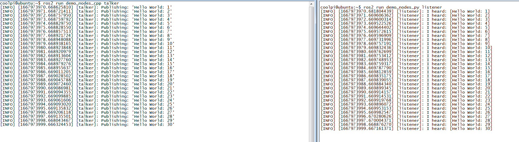
小乌龟测试:
两个shell终端分别输入下面两条指令$ ros2 run turtlesim turtlesim_node $ ros2 run turtlesim turtle_teleop_key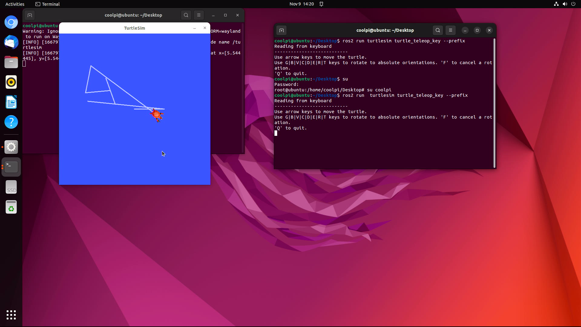
-
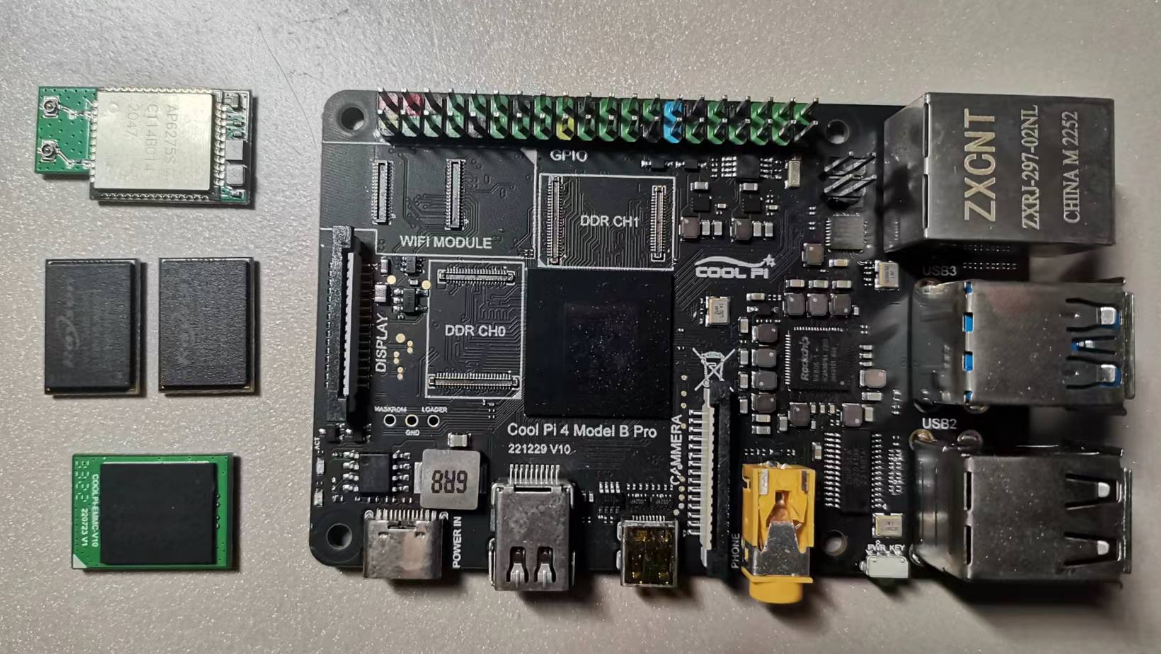
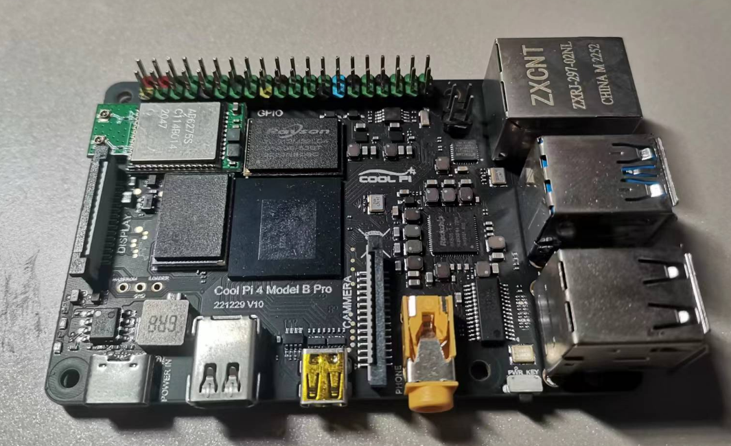
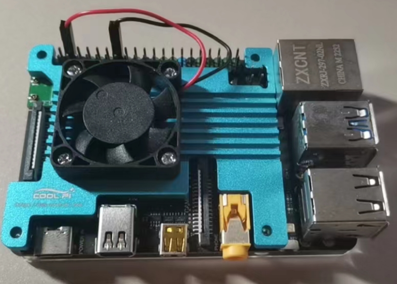
CoolPI 4B-PRO Product Introductionposted in News
-
Picture first
-
4G-32G Memory Capacity Replacement.
-
The WIFI module is replaceable and supports models such as 2.4G 5G WIFI6.
-
EMMC module supports up to 256G.
-
-
RE: 自定义bootloaderposted in Pi 4B
@zehui
启动的流程是一样的,目前uboot的结构如下:FIT description: FIT Image with ATF/OP-TEE/U-Boot/MCU Created: Wed Feb 28 09:32:41 2024 Image 0 (uboot) Description: U-Boot Created: Wed Feb 28 09:32:41 2024 Type: Standalone Program Compression: uncompressed Data Size: 1389728 Bytes = 1357.16 KiB = 1.33 MiB Architecture: AArch64 Load Address: 0x00200000 Entry Point: unavailable Hash algo: sha256 Hash value: e8eeabe5b2891390396b4cb77a33c5bb8da03b1da33a64274a077cf386f2b5aa Image 1 (atf-1) Description: ARM Trusted Firmware Created: Wed Feb 28 09:32:41 2024 Type: Firmware Compression: uncompressed Data Size: 200008 Bytes = 195.32 KiB = 0.19 MiB Architecture: AArch64 Load Address: 0x00040000 Hash algo: sha256 Hash value: c902200be1343fe569e54778c286005b1c6163606664c463a24d787be4376966 Image 2 (atf-2) Description: ARM Trusted Firmware Created: Wed Feb 28 09:32:41 2024 Type: Firmware Compression: uncompressed Data Size: 24576 Bytes = 24.00 KiB = 0.02 MiB Architecture: AArch64 Load Address: 0xff100000 Hash algo: sha256 Hash value: 225d6bf0712f850648223365ba06a73ba5f6315fb8a9580f23ab48ece795f91e Image 3 (atf-3) Description: ARM Trusted Firmware Created: Wed Feb 28 09:32:41 2024 Type: Firmware Compression: uncompressed Data Size: 24576 Bytes = 24.00 KiB = 0.02 MiB Architecture: AArch64 Load Address: 0x000f0000 Hash algo: sha256 Hash value: aa71013e72d7ab4be264c1093b155ef06e65d0a263d552be25b13c8ddf285586 Image 4 (optee) Description: OP-TEE Created: Wed Feb 28 09:32:41 2024 Type: Firmware Compression: uncompressed Data Size: 465304 Bytes = 454.40 KiB = 0.44 MiB Architecture: AArch64 Load Address: 0x08400000 Hash algo: sha256 Hash value: 66e30bf9e879405a49797aaa6c08ca1c41aa325443e910af42e3df309e65909b Image 5 (kern-fdt) Description: cp4/uboot.dtb Created: Wed Feb 28 09:32:41 2024 Type: Flat Device Tree Compression: uncompressed Data Size: 141854 Bytes = 138.53 KiB = 0.14 MiB Architecture: AArch64 Hash algo: sha256 Hash value: ba43bc47ab29f0cbcba25658712ac3d3c6349a30486c76d5b720310e58f02de3 Image 6 (fdt) Description: U-Boot dtb Created: Wed Feb 28 09:32:41 2024 Type: Flat Device Tree Compression: uncompressed Data Size: 7065 Bytes = 6.90 KiB = 0.01 MiB Architecture: AArch64 Hash algo: sha256 Hash value: 987a71d492c0045c4964bbed7799da0eee5276a2b60b5a1335fc2d37fdfcf944 Default Configuration: 'conf' Configuration 0 (conf) Description: rk3588s-cp4 Kernel: unavailable Firmware: atf-1 FDT: fdt kern-fdt Loadables: uboot atf-2 atf-3 optee -
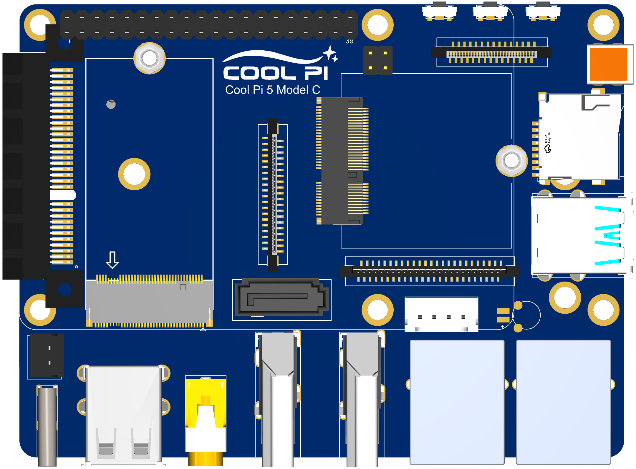
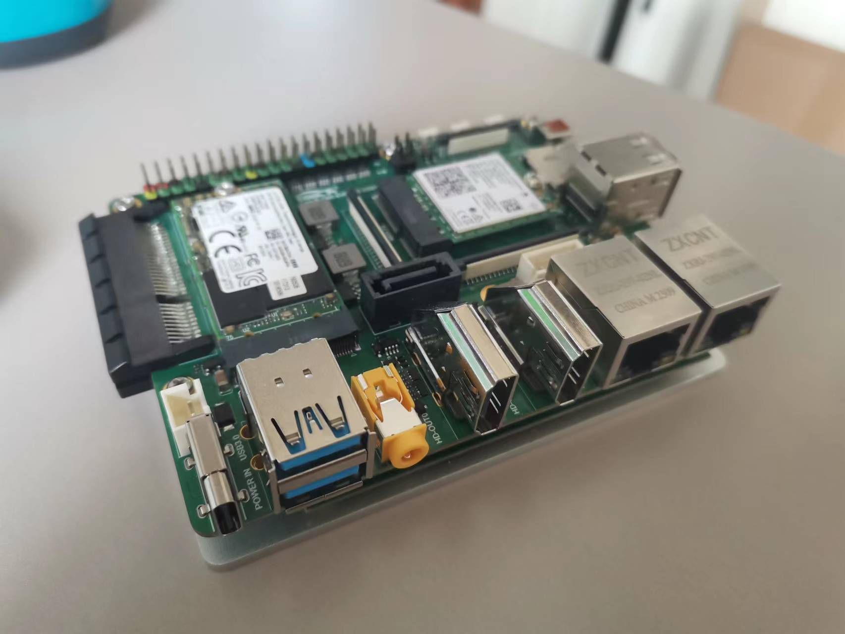
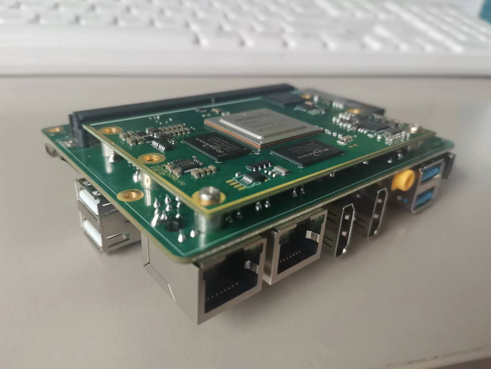
Introduction to COOL PI CM5 interfaceposted in Pi CM5
Top-level interface
-
The 2X20 pin interface is compatible with CP4 and integrates multiple UART, I2C, SPI, CAN and other functions.
-
Three function keys are PWR, RST and LOADER.
-
2X2 PIN POE connector,such as CP4.
-
30pin fpc vertical connector can directly drive standard 30PIN EDP interface LCD. Resolution up to 3840 * 2160
-
The MICRO HDMI-RX interface can support up to 4KP60 video signal input.
-
TF card with self-locking.
-
Two native USB3.0 interfaces, one of which supports OTG function.
-
Two Gigabit Ethernet interfaces, one of which supports POE function.
-
Two HDMI2.1 interfaces with a maximum resolution of 8K.
-
Stereo headphone stand with MIC input function.
-
Two native USB2.0 interfaces.
-
One TYPEC power supply interface, consistent with CP4.
-
The external power interface of 2PIN can support DC power input.
-
1 standard PCIE 4X connector, currently only supports PCIE3.0 2X/1X mode.
-
SSD interface, only PCIE-M2-2242 size hard disk is supported.
-
Standard 7PIN SATA3.0 interface, 4PIN power interface.
-
M.2 WIFI module interface, supporting multiple general WIFI modules.
-
Dual MIPI LCD interfaces support simultaneous output of two MIPI interface LCDs. The resolution of a single LCD is up to 1920 * 1200. It supports the MIPI DSC function.
-
Four independent MIPI camera interfaces support four camera inputs at the same time. It can be configured as 2X4LINE or 4X2LINE mode.
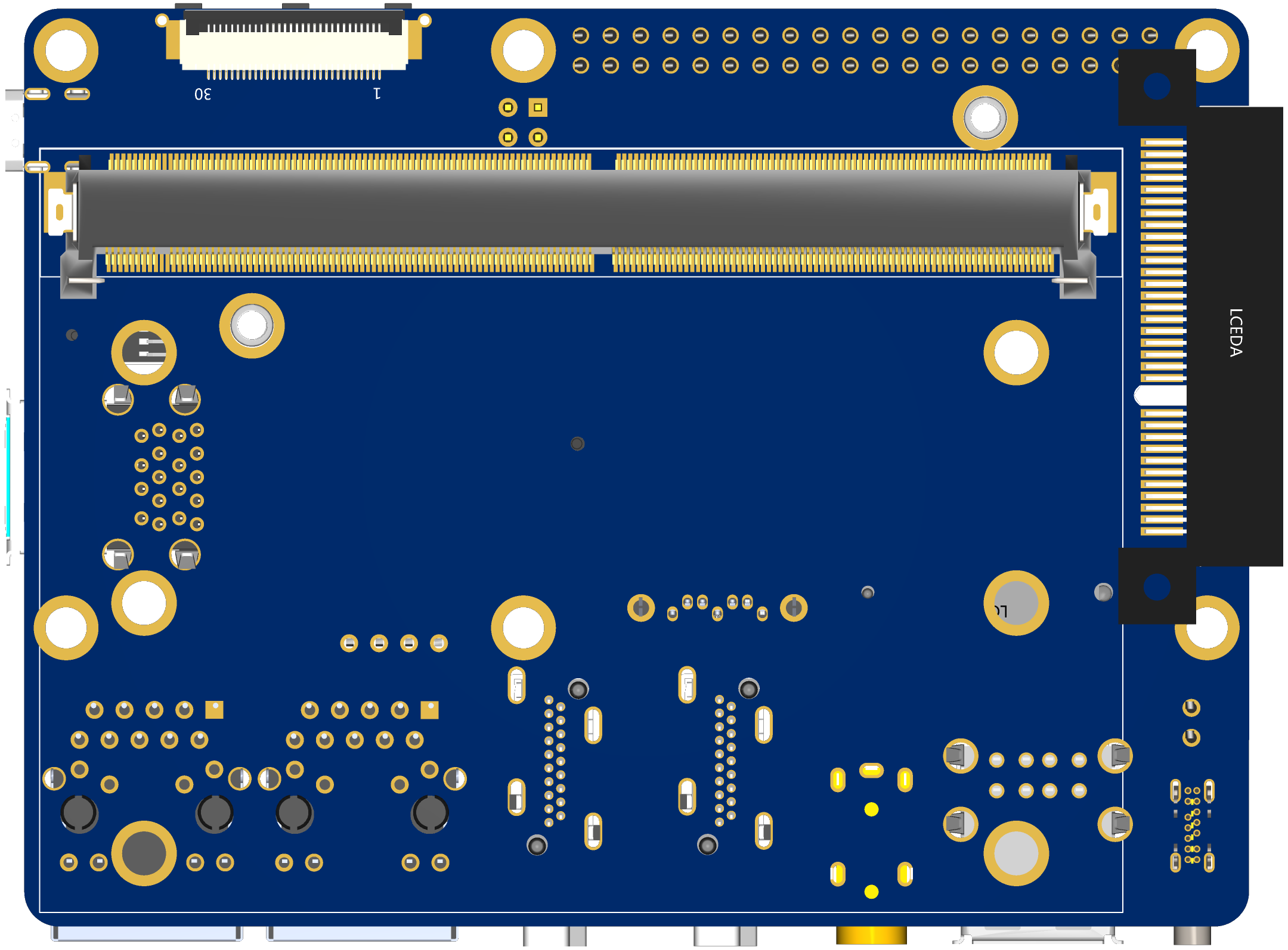
Bot-level interface
-
One 30PIN EDP interface can directly drive LCD output.
-
MXM 314PIN core board connector.
Welcome to put forward good suggestions. We can consider revising them.
-
-
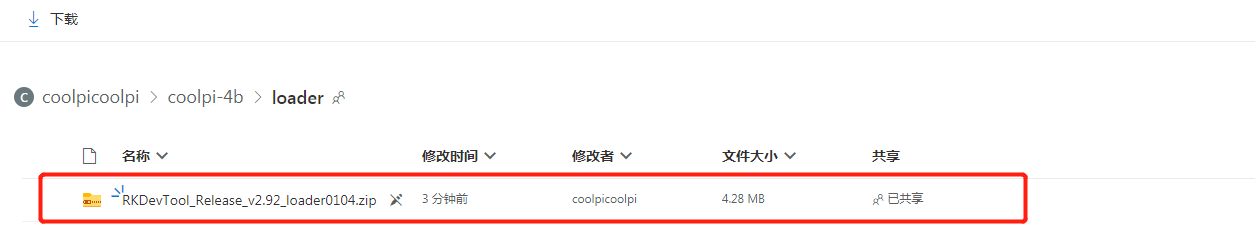
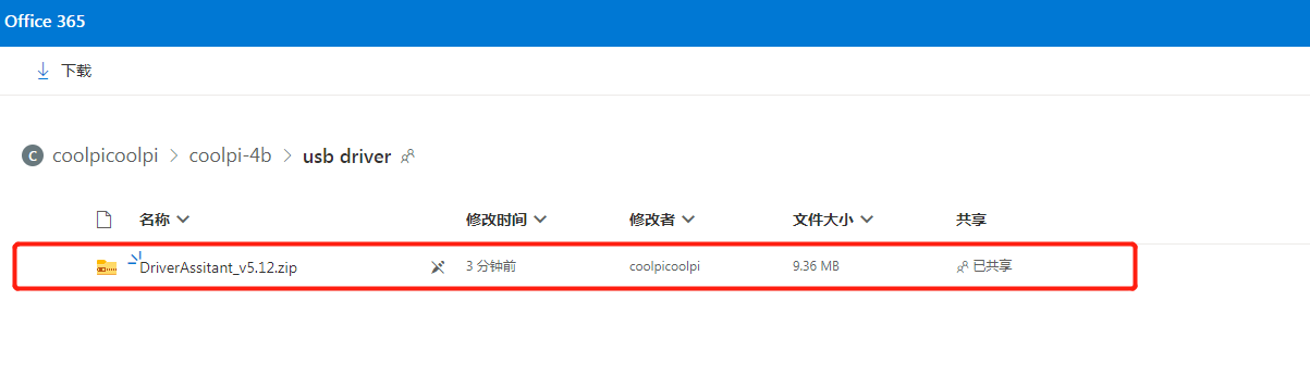
How to upgrade the boot loader of coolpi 4b?posted in Pi 4B
If you need to boot armbian normally, you need to update the loader file to version 0104.
Follow the steps below to update the loader:
-
Download the latest loader file One Drive
![5594e1d4-3a7b-46fc-a7b5-2a9fe418dfc0-image.png]
-
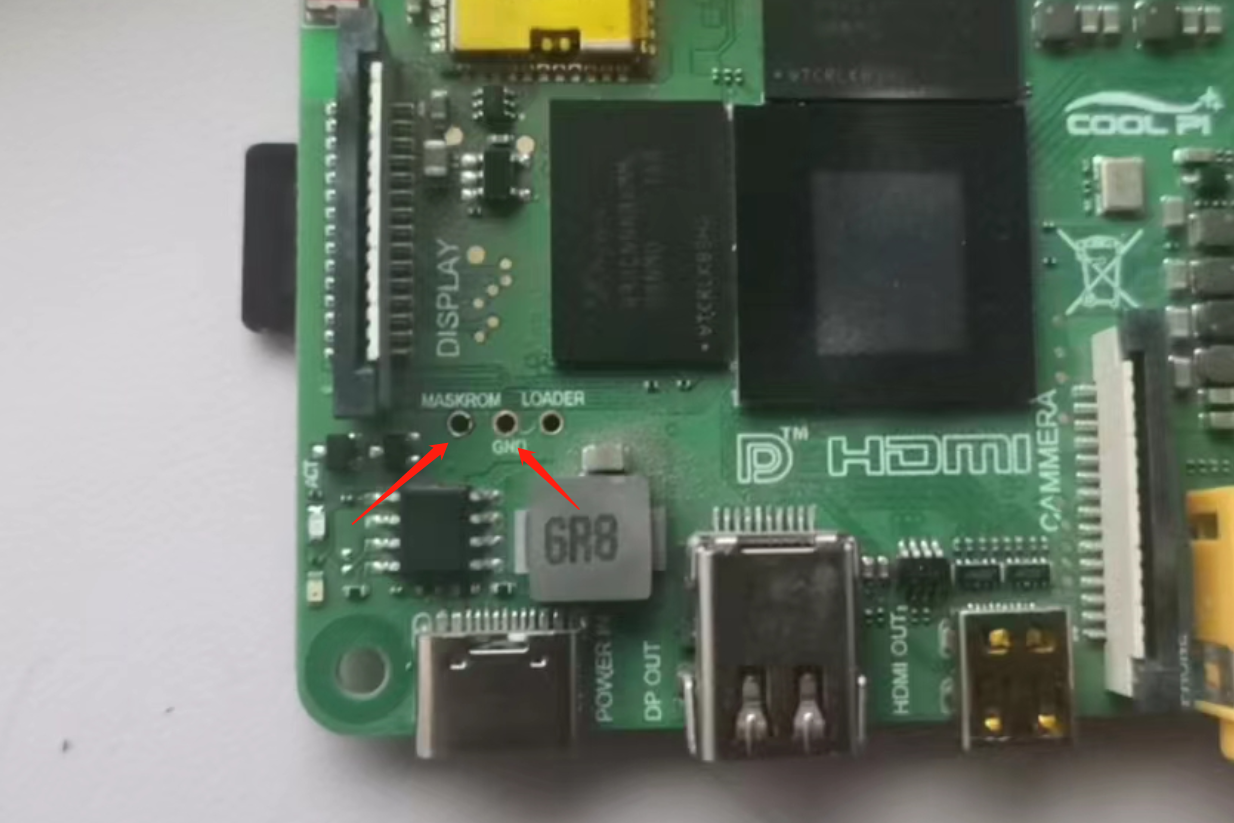
Short the 2 pins shown by the arrow.
-
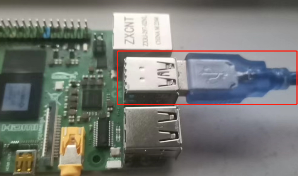
The USB interface and computer connection.
-
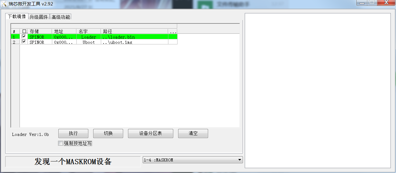
Plug in the power supply and open the upgrade software. The machine enters the maskrom upgrade mode.
-
choose to write by address

-
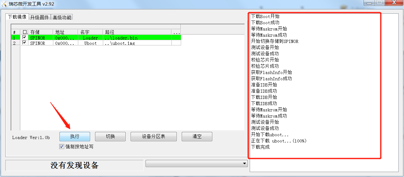
Click Execute to complete the loader update.
-
If the computer prompts that the USB driver cannot be found, please download and install the driver software first.One Drive
-
-
RE: Cool Pi ARM Notebook Previewposted in News
@大法师 补充一张内部图片,支持全国产化定制。
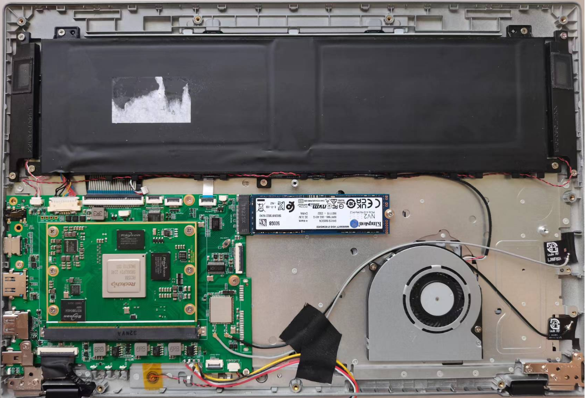
统信专业版,QQ 微信 WPS 邮件 CAD等软件流畅运行,办公追剧毫无压力。
-
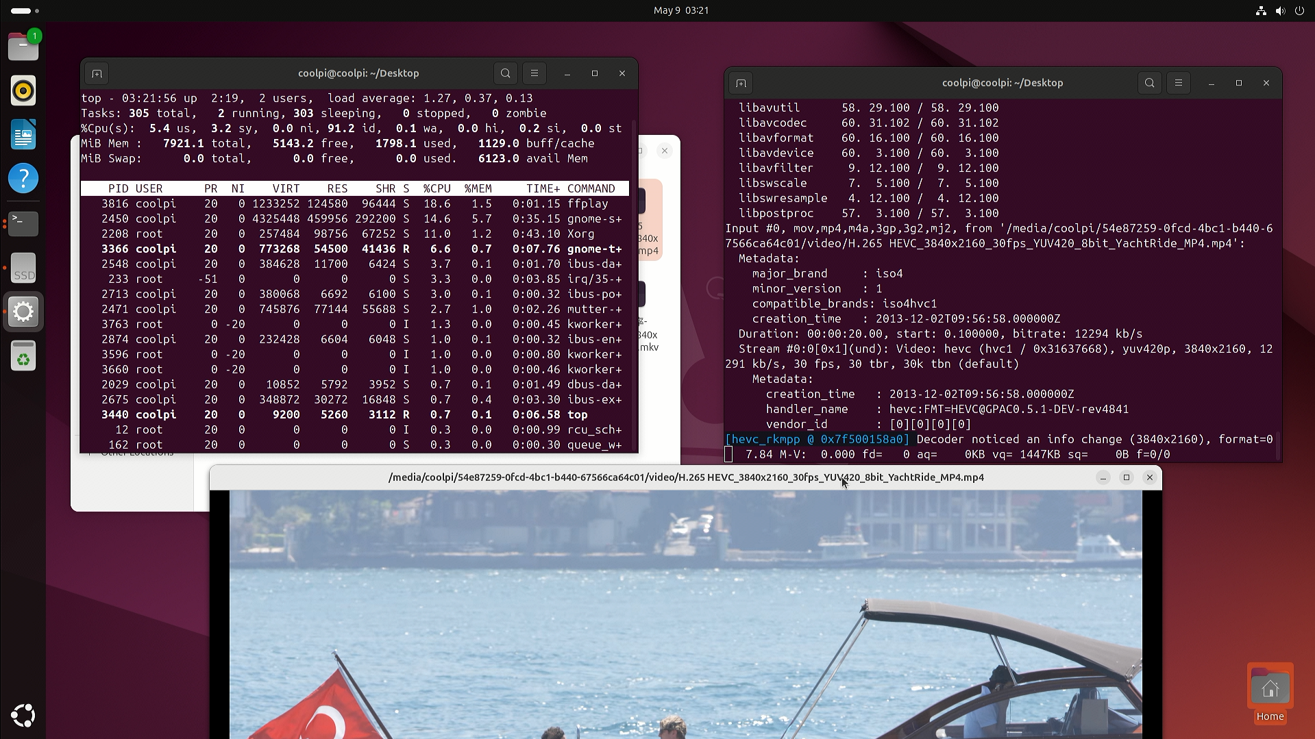
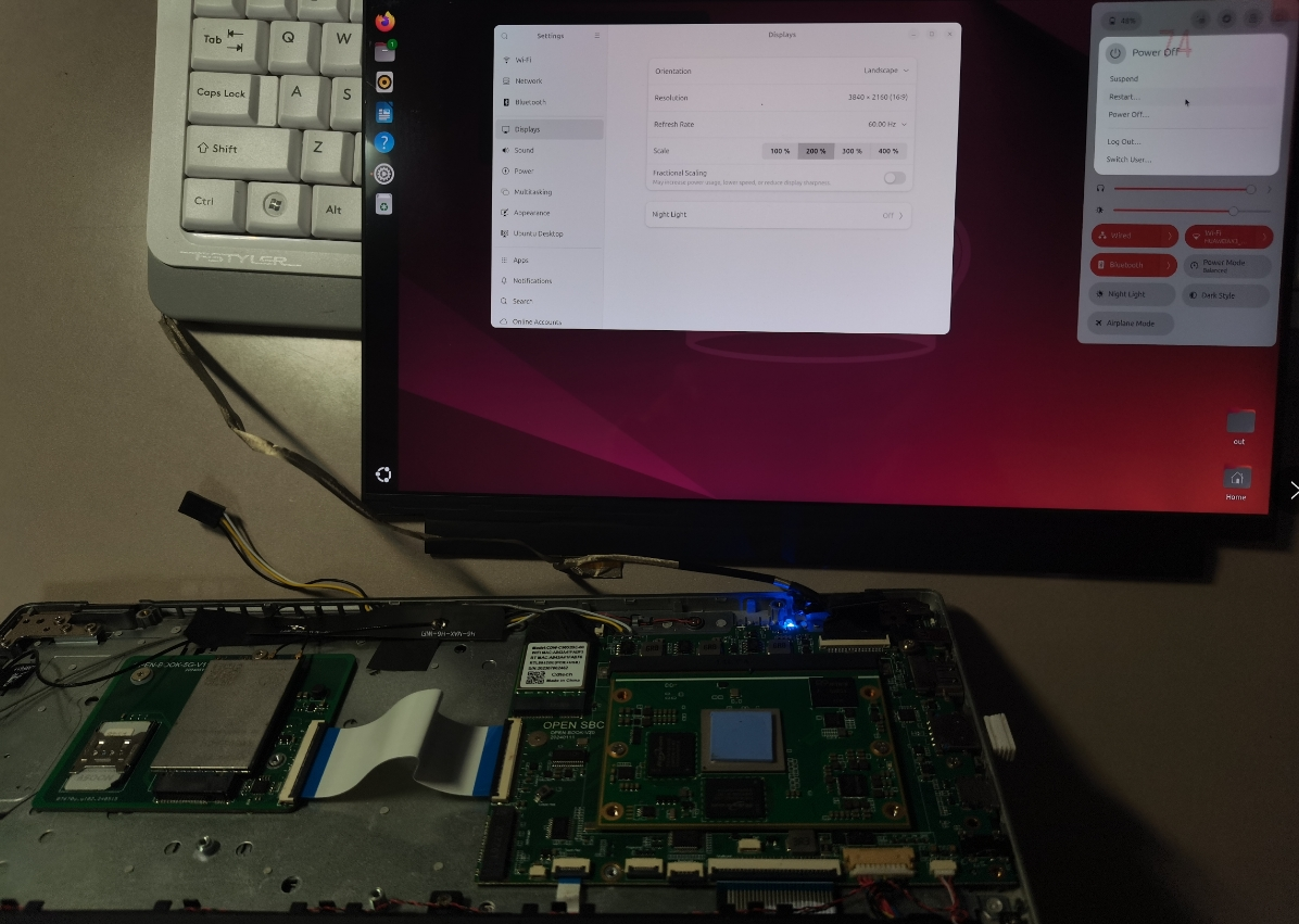
Cool Pi Cm5-Laptop Linux Quick Start Guideposted in PI CM5 Laptop
Machine Introduction
COOLPI CM5 open-source notebook is a product that combines high performance, portability, and open-source spirit. It not only meets the basic computing needs of users, but also provides an ideal platform for those who enjoy free exploration and technological creation.
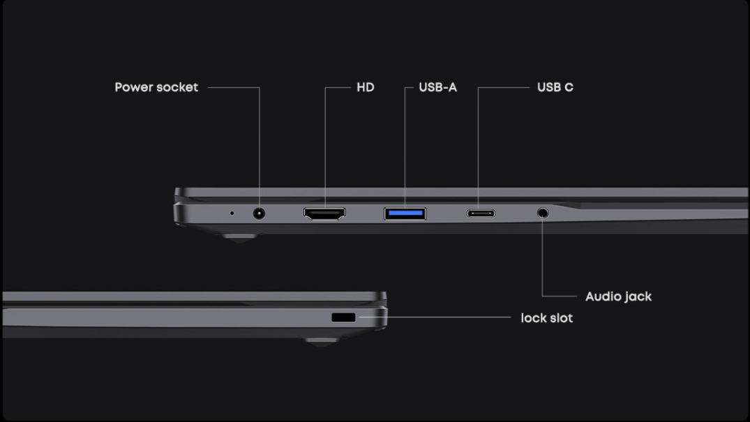
Installing the system
The machine is installed with Ubuntu 22.04 system by default at the factory. If users need other versions, they can update them according to the following tutorial.
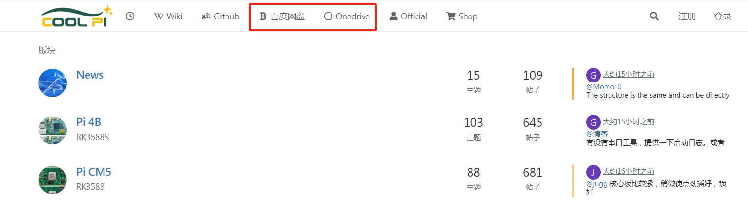
The default username for the machine is: coolpi Password: 123Download image
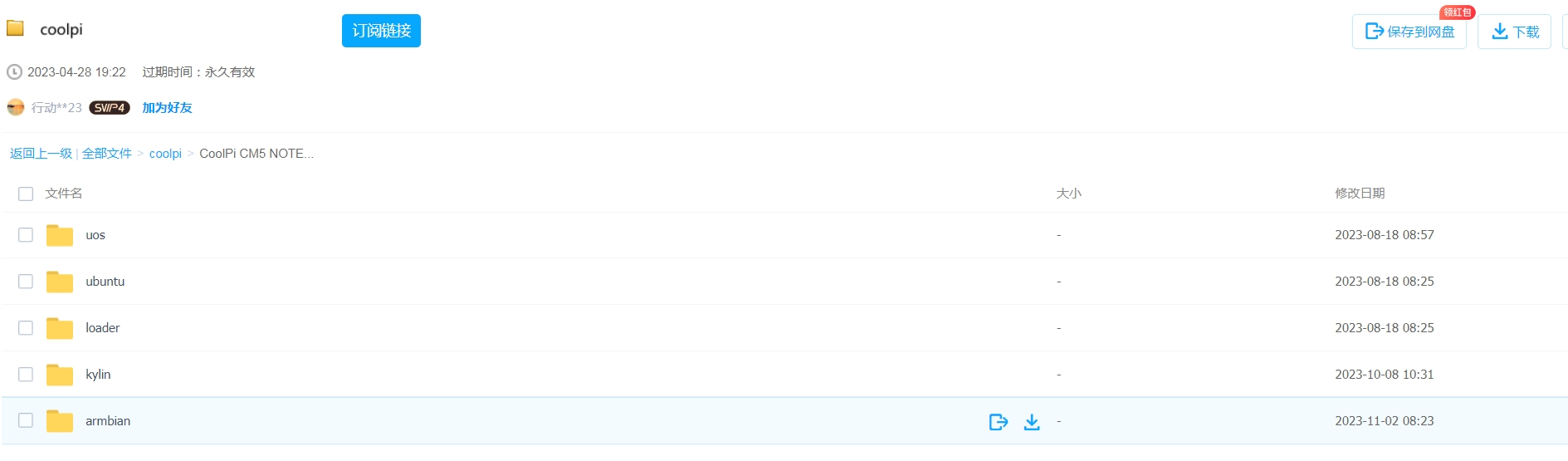
As shown in the following figure: System images can be downloaded through 百度网盘 or Onedrive.
Select the image that needs to be updated, and the image type will continue to be updated.
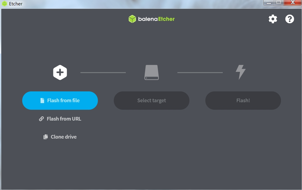
Download tools
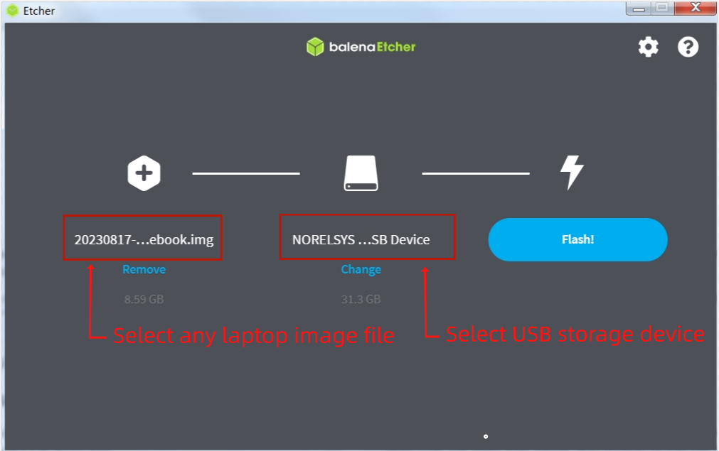
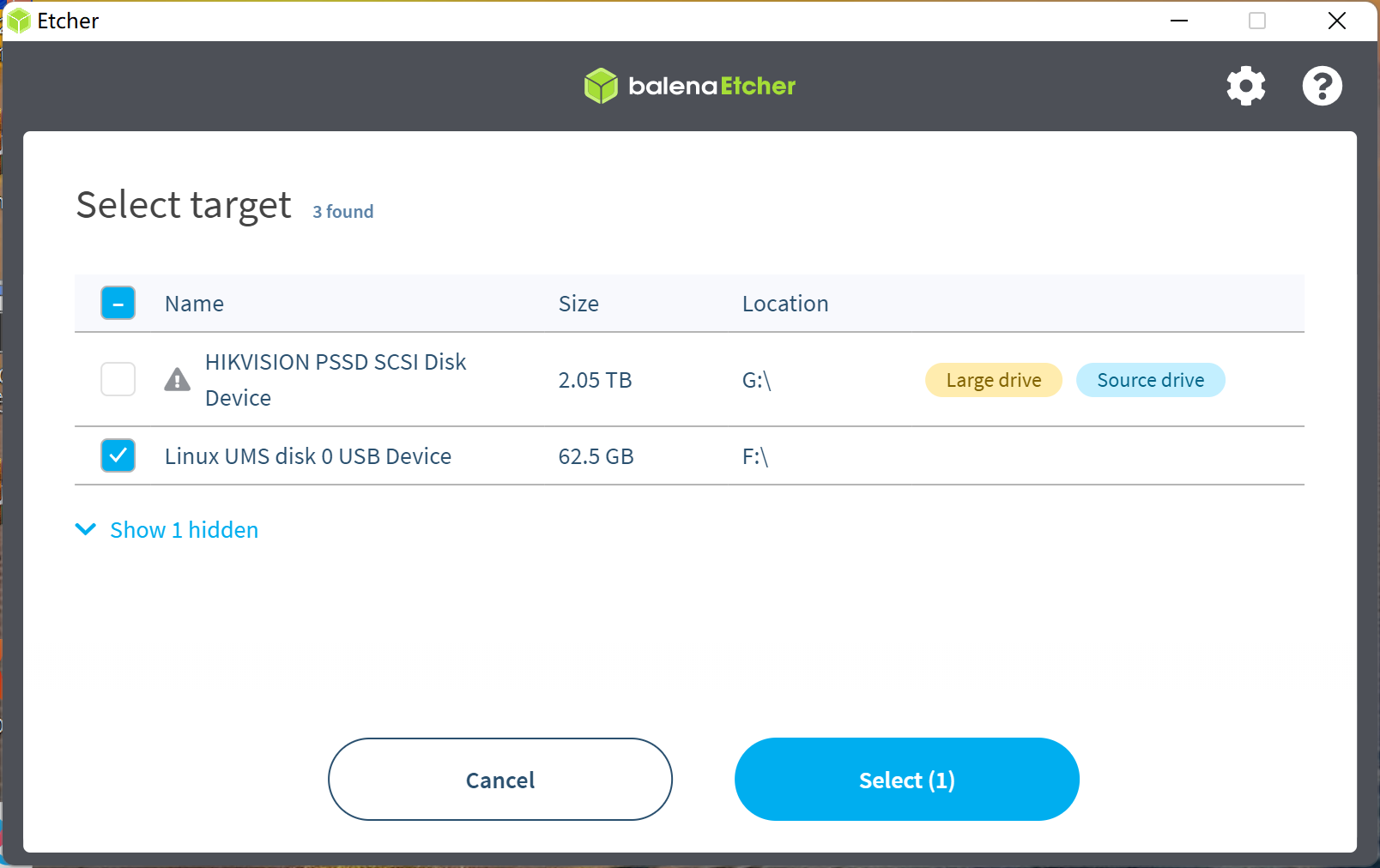
Coolpi defaults to using Etcher to update system images, which can be obtained through Baidu Cloud, Onedrive, or the official website.
Machine enters UMS mode
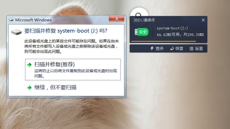
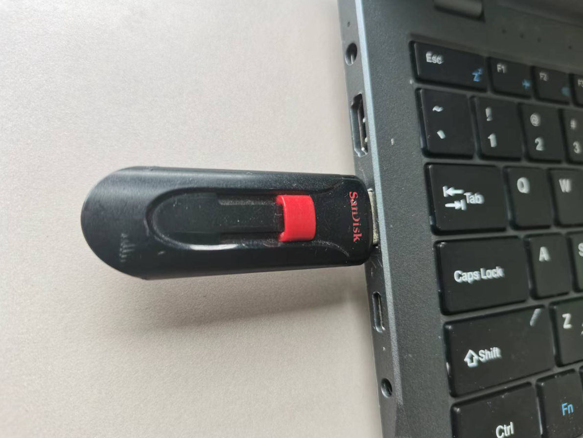
The Type-C port of the machine is connected to the computer. When the Coolpi laptop is turned off, it can quickly press the power button multiple times, usually no less than 8 times, and the machine will enter MUS mode. The computer will recognize an icon for a USB drive. As shown in the following figure:
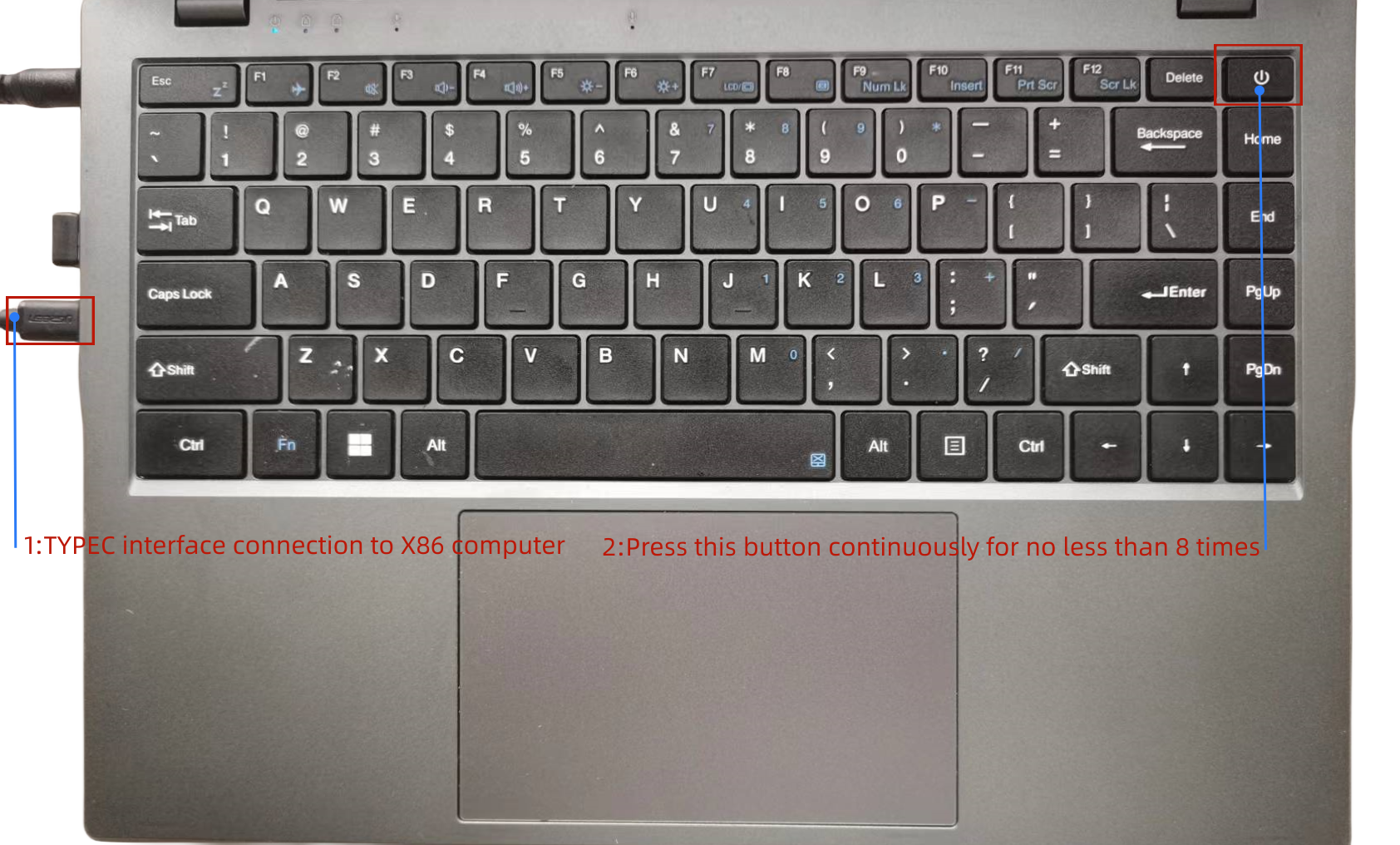
The X86 computer will recognize a UMS device.
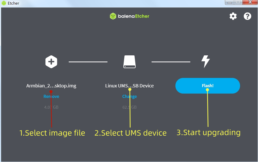
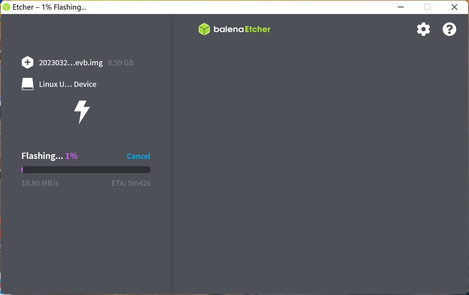
Load image and flash
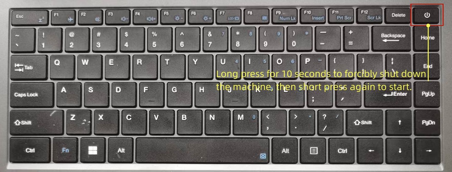
Follow the three steps shown in the figure to burn the image file. After the burning is completed, a forced restart is required. The method of forced power down is to continue holding down the power button for 10 seconds.
After downloading, restart the machine as shown in the following figure.
Update kernel
The kernel of Coolpi will continue to be updated, and users can also compile the mainline kernel themselves to upgrade the machine, following the steps below. The compilation of the kernel part in the following figure is completed on the Coolpi laptop, and users can also cross compile on the X86 computer. The method and steps are the same.
Synchronize kernel
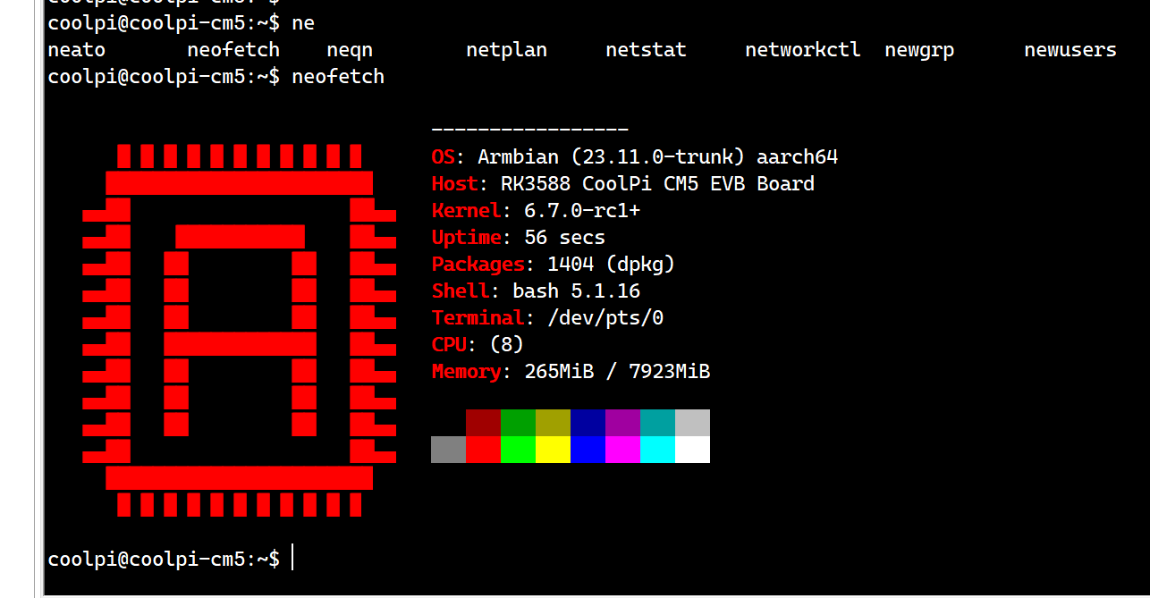
sudo apt-get update
sudo apt-get upgrade
sudo apt-get install git
git clone https://github.com/yanyitech/coolpi-kernel.git
Compile kernel
First, install the git toolkit, and it is best to update the system to the latest version before installation. Install some kernel dependent packages, then run the compilation script, enter numbers to select the corresponding machine model, and the compilation can proceed normally.
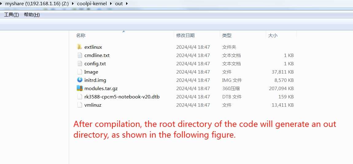
sudo apt-get install flex bison libssl-dev
sudo ln -s /usr/bin/python3.10 /usr/bin/python
cd coolpi-kernel
./build-kernel.sh
Welcome to using Coolpi Development Board!
------------------------------------------
Please enter a number to select your machine

1. cp4b
2. cp4b-hdmi-in
3. cm5-evb
4. cm5-evb-v11
5. cm5-minipc
6. cm5-notebook
7. cm5-notebook-v20
8. cm5-8uart
9. cpnano
10. exit

Enter option number: 7
Upgrade machine kernel
After the normal compilation of the kernel, an out folder will be generated with the directory, which contains all the files required by the kernel. You can update the newly compiled kernel to the machine by using the following command.
Use the following command to update the kernel.sudo cp ./out/* /boot/firmware -R sudo rm /lib/modules/* -R sudo tar -zxvf ./out/modules.tar.gz -C /lib/ sync sudo rebootIf the kernel was cross compiled using X86 machines, the kernel can be updated using the following methods:
- Use the Samba shared folder to copy the compiled files to the Coolpi machine.
- Use mobile storage devices such as USB drives to copy.
- The coolpi machine enters UMS mode, connects to the X86 computer, enters the USM mobile disk, deletes all files, and copies all files in the generated out directory to the UMS mobile disk. Then force a restart of the Coolpi laptop.
Change the startup logo
Users can update the startup logo of the machine by copying files, using the following command.
sudo cp ./logo.bmp /boot/firmware
sync
sudo reboot
Below is a standard format for a logo file that users can download and modify. Please note that the pixel size, name, and format of the file should not be changed.
logo.zipFrequently asked questions
The machine cannot enter UMS mode
Due to incomplete image updates, the partition table of EMMC is damaged, and the machine cannot enter UMS burning mode. The following methods can be used to repair the EMMC partition table.
- A USB interface mobile storage device with a capacity of no less than 16GB, and an X86 computer can burn any image to the USB device through ETCHER software.
- Insert USB storage device into the USB interface of the Coolpi laptop
- The machine will first start from the USB storage device when turned on. Then enter the system. Format EMMC using the following command.
sudo mkfs.ext4 /dev/mmcblk0 -
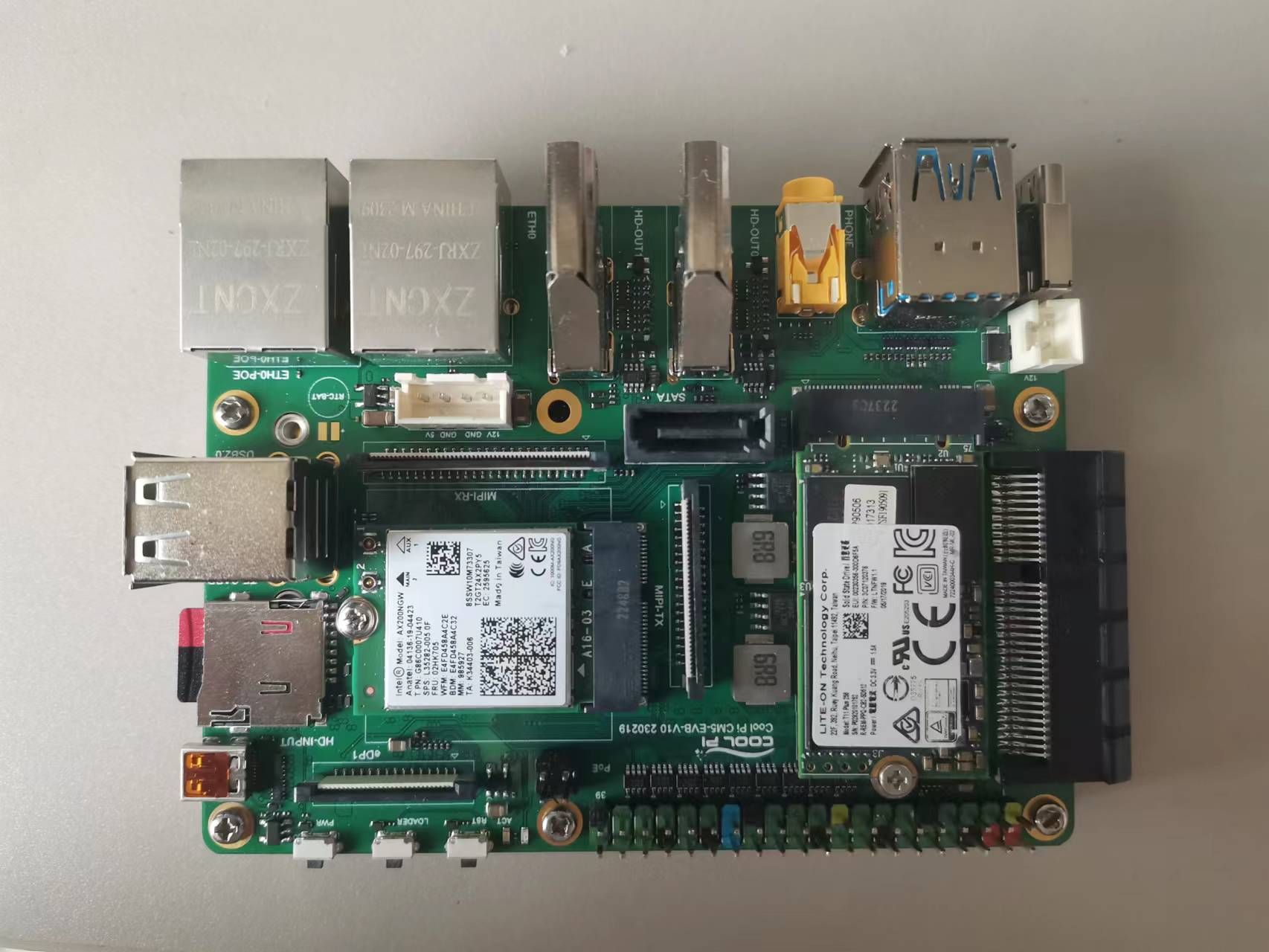
CM5-EVB Commissioning Descriptionposted in Pi CM5
-
Product image
-
All interface functions have been debugged and are currently undergoing performance optimization.
-
It is expected to be sold normally in early April.
-
-
Coolpi uses UMS to update the systemposted in Pi 4B
Coolpi supports UMS to update emmc firmware, as follows:
- Update the latest versions of loader and uboot images. You can also synchronize uboot code and compile it yourself.
git clone https://github.com/yanyitech/coolpi-loader cd coolpi-loader ./build-uboot.sh cp4b- Connect a dual A port USB cable to the computer and the upper USB 3.0 interface. Plug in the power and press the power button three times, and the machine will enter UMS mode.
- Use Etcher software to update the software.
-
RE: Cool Pi ARM Notebook Previewposted in News
@ngavarta
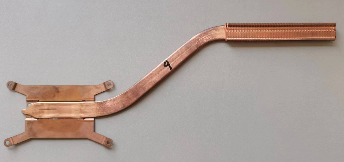
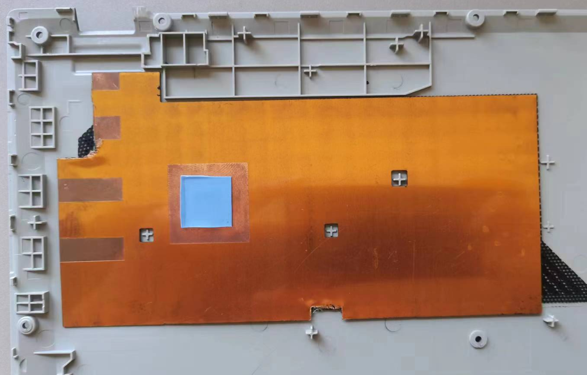
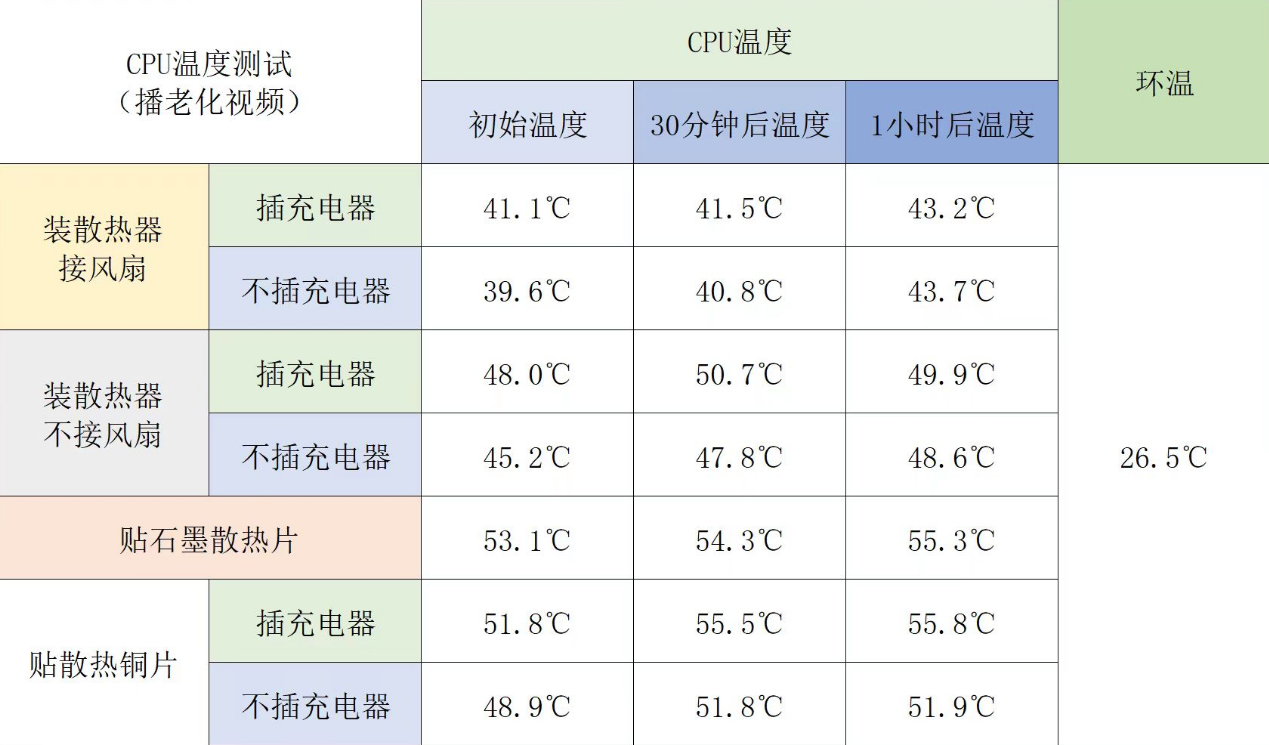
In the early stage, there was a plan to use a copper tube heat sink as shown in the figure below for heat dissipation between the CM5 and the fan. Later, the machines shipped were changed to passive graphite copper sheet heat dissipation.
Copper tube radiator:
Graphene+copper sheet radiator:
Temperature test data:
-
RE: Booting from USB driveposted in PI CM5 Laptop
- It is recommended to use a USB 2.0 interface driver as the boot disk.
- You can also put the system into single user mode and set the ROOT password, which will involve modifying CMDLINE.
-
coolpi is a cool computerposted in Pi CM5
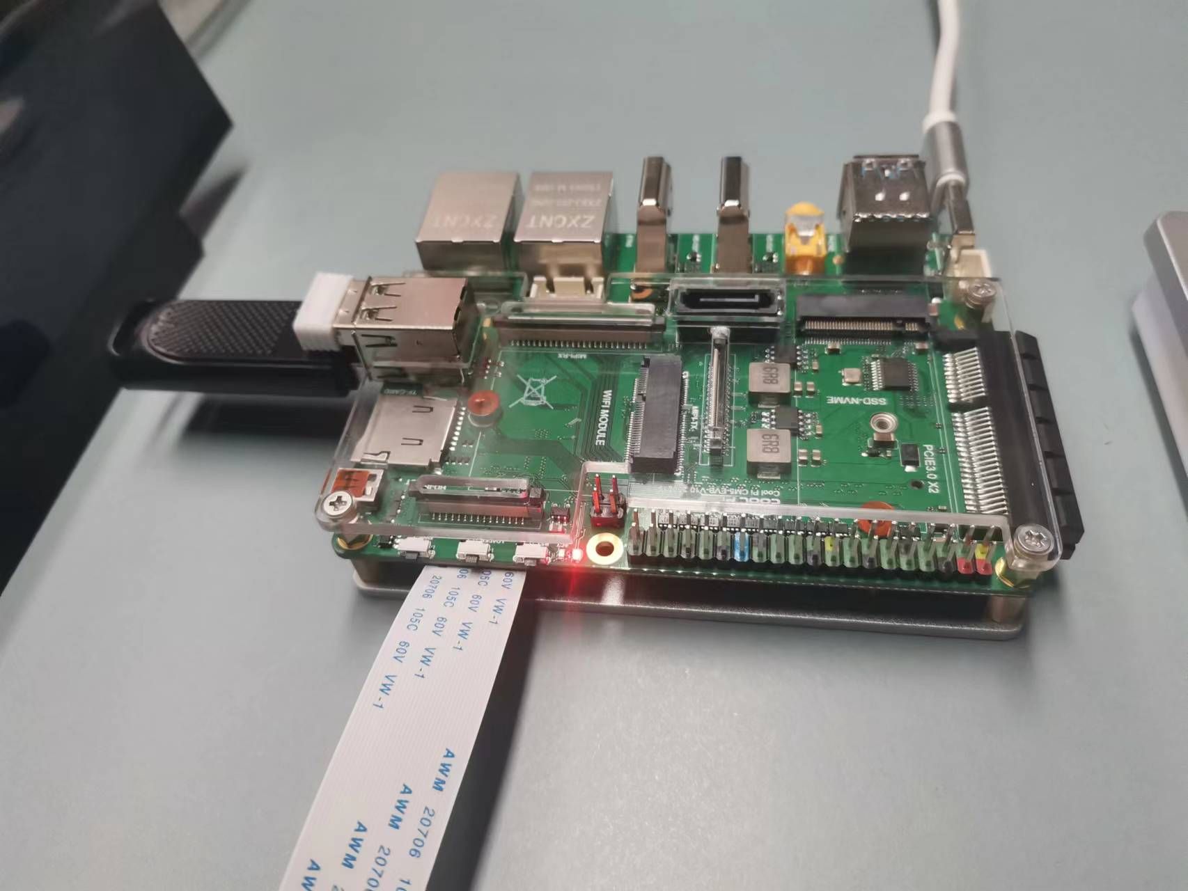
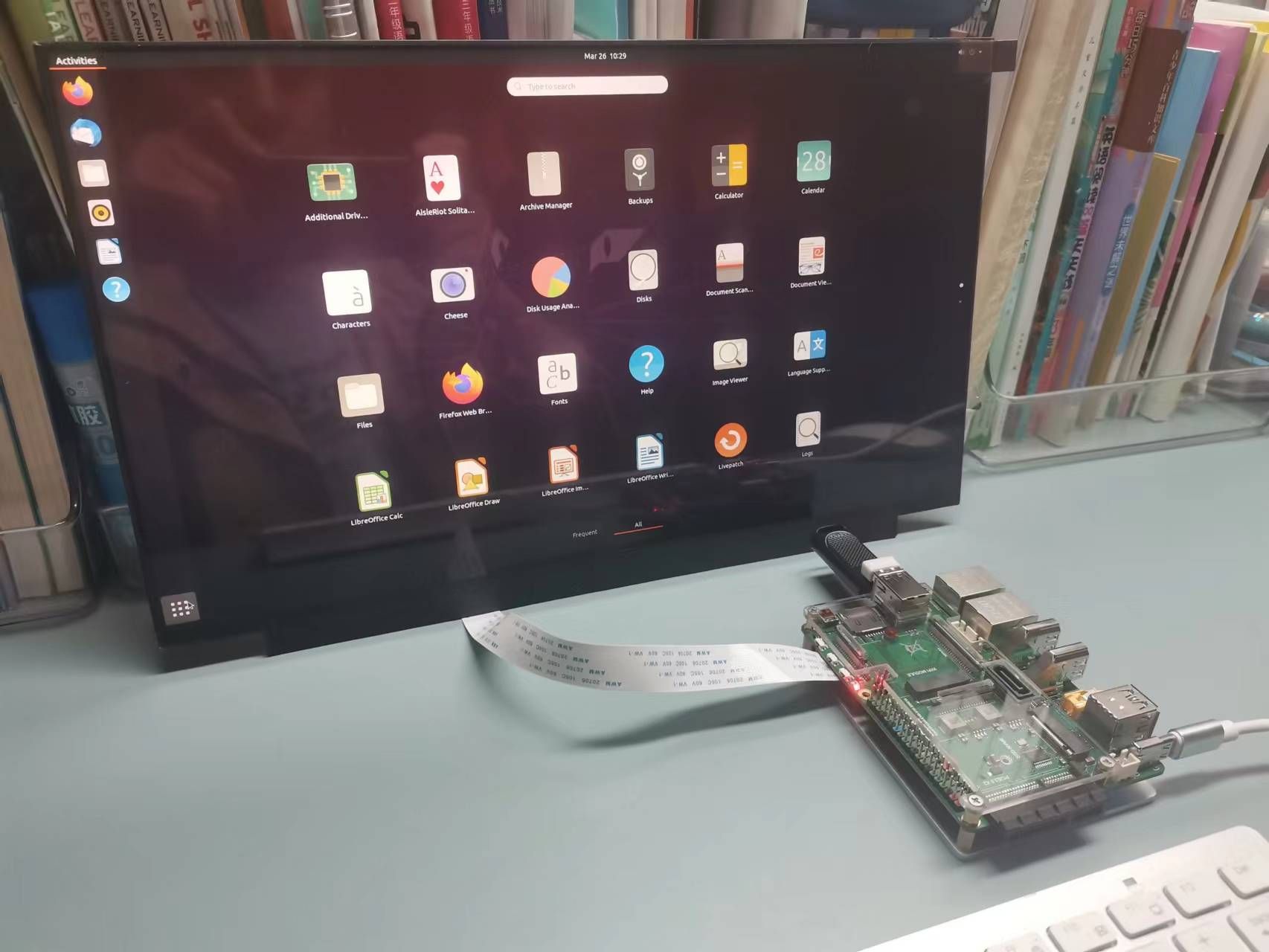
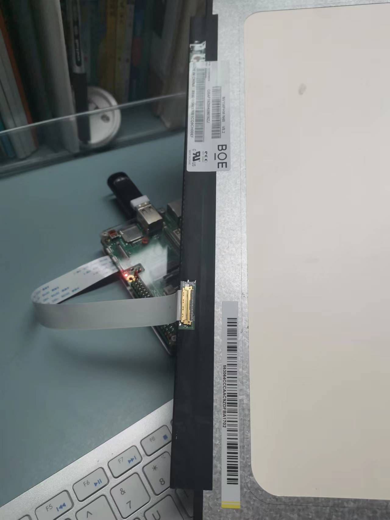
The CM5-evb board has two native eDP interfaces, designed according to the standard 30PIN eDP interface, and can directly drive an eDP LCD without any conversion. Interface integrated backlight control circuit. LCD backlight brightness adjustment can be achieved.
-
RE: CoolPi 4B: Change output pins of i2c3 and i2c5posted in Pi 4B
@maxpol
Refer to the following documents:
https://www.cool-pi.com/topic/70/coolpi-4b硬件扩展三-i2c?_=1695004097775 -
RE: Cool Pi ARM Notebook Previewposted in News
@Momo-0
The structure is the same and can be directly replaced, then upgrade to the latest V20 software. -
RE: Ubuntu 24.04 for CM5 Laptopposted in PI CM5 Laptop
@Rock
At present, the maximum version supported by coolpi laptop is 23.04. Ubuntu 24.04 has just been released a few days ago and adaptation will take some time. It is expected that a version will be released in May. Thank you for your support. -
RE: How to drive non-standard resolution HDMI displaysposted in Pi CM5
@george Add 5.5inch HDMI AMOLED edid
https://www.waveshare.net/shop/5.5inch-HDMI-AMOLED.htm
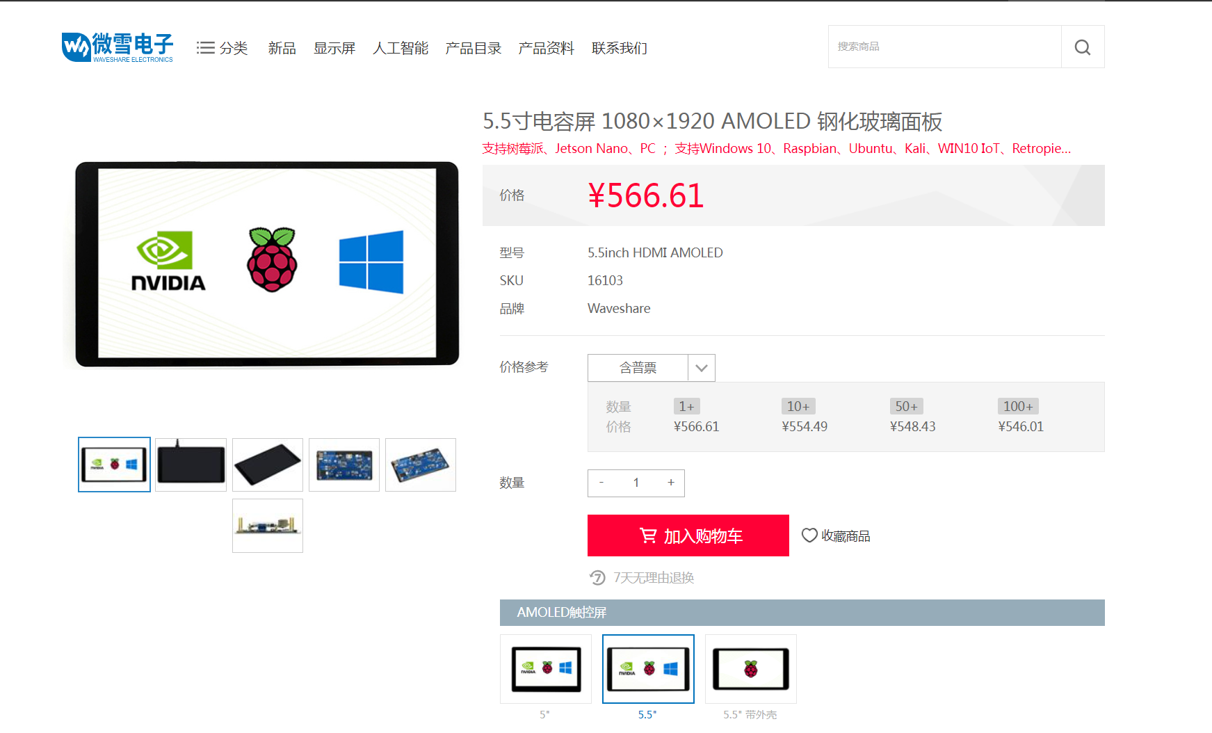
diff --git a/drivers/gpu/drm/drm_edid.c b/drivers/gpu/drm/drm_edid.c
index 4fdfb41b91e1..b1171d8cbf2d 100644
--- a/drivers/gpu/drm/drm_edid.c
+++ b/drivers/gpu/drm/drm_edid.c
@@ -575,6 +575,14 @@ static const struct drm_display_mode drm_dmt_modes[] = {
        { DRM_MODE("4096x2160", DRM_MODE_TYPE_DRIVER, 556188, 4096, 4104,
                   4136, 4176, 0, 2160, 2208, 2216, 2222, 0,
                   DRM_MODE_FLAG_PHSYNC | DRM_MODE_FLAG_NVSYNC) },
+       /* 0x59 - 3840x1100@59.998Hz RB */
+       { DRM_MODE("3840x1100", DRM_MODE_TYPE_DRIVER, 282890, 3840, 3888,
+                  3920, 4100, 0, 1100, 1103, 1108, 1150, 0,
+                  DRM_MODE_FLAG_PHSYNC | DRM_MODE_FLAG_NVSYNC) },
+       /* 0x60 - 1080x1920@60Hz RB */
+       { DRM_MODE("1080x1920", DRM_MODE_TYPE_DRIVER, 137520, 1080, 1112,
+                  1144, 1200, 0, 1920, 1928, 1932, 1936, 0,
+                  DRM_MODE_FLAG_NHSYNC | DRM_MODE_FLAG_NVSYNC) },
 };
-
RE: CoolPi 4B: Change output pins of i2c3 and i2c5posted in Pi 4B
@maxpol I2C3 I2C5 cannot be changed to other pinsOf course, you can try opening other I2C channels.
-
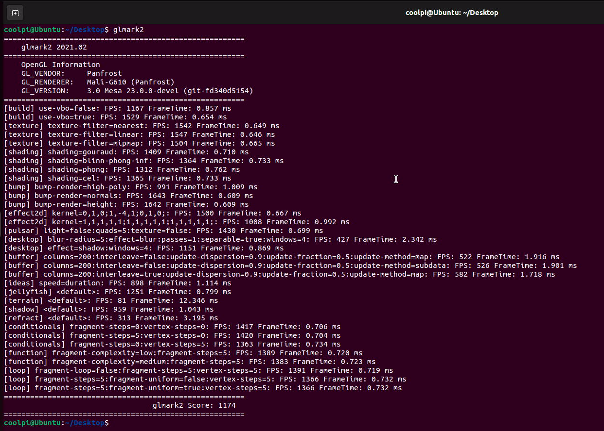
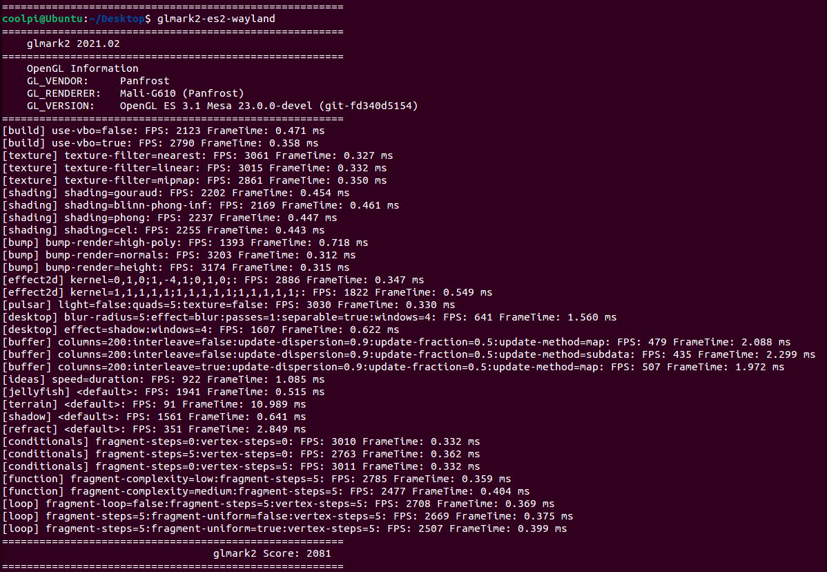
Coolpi 4b with Ubuntu22 running panfrost gpu driver performance testingposted in Ubuntu
CPU
测试方法:
sudo apt install sysbench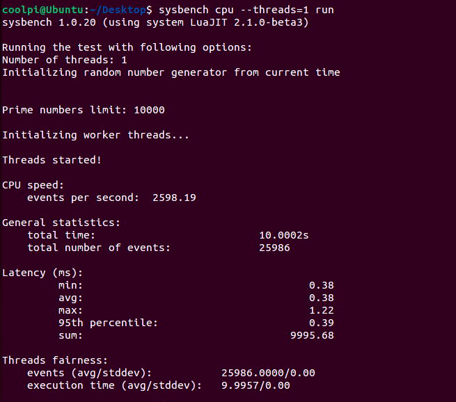
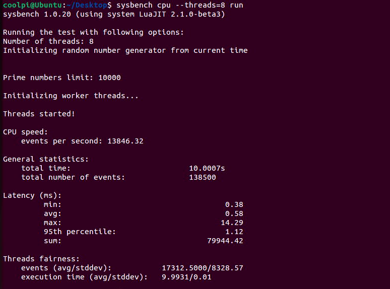
RK3588S单核心每秒事件数2598,8核每秒事件数13846;同步对比 i7-7700 ,单核每秒事件数1438,8核每秒事件数8469。可见ARM在CPU方面并不比X86弱。GPU
测试方法:
sudo apt-get install glmark2* -yX11 gl
X11 gles 3.1
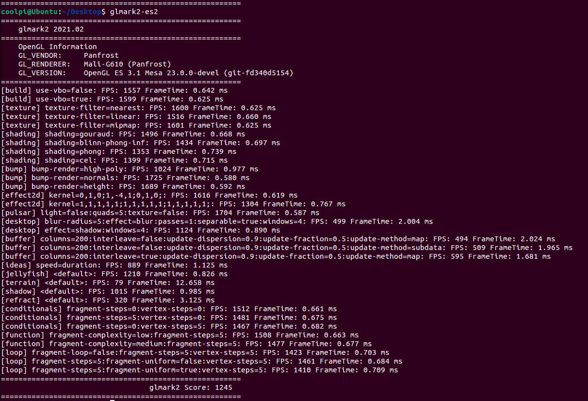
WAYLAND gl
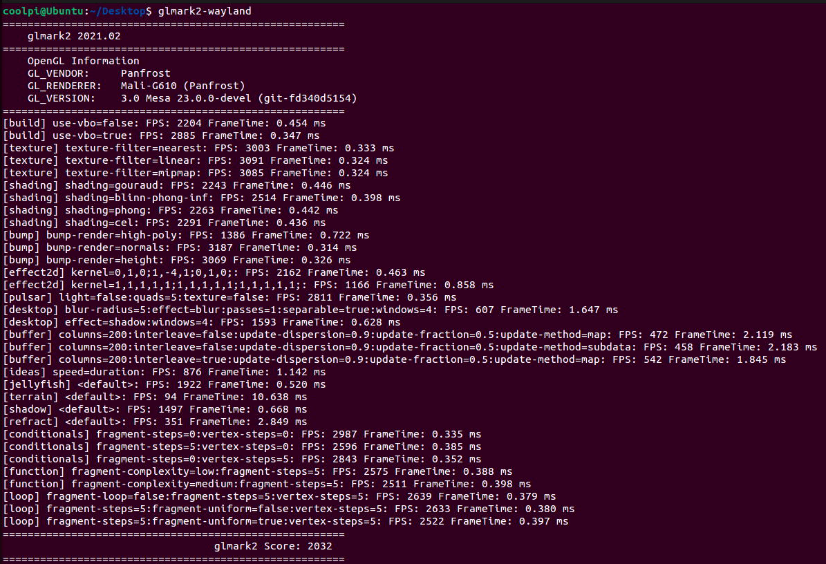
WAYLAND gles 3.1
-
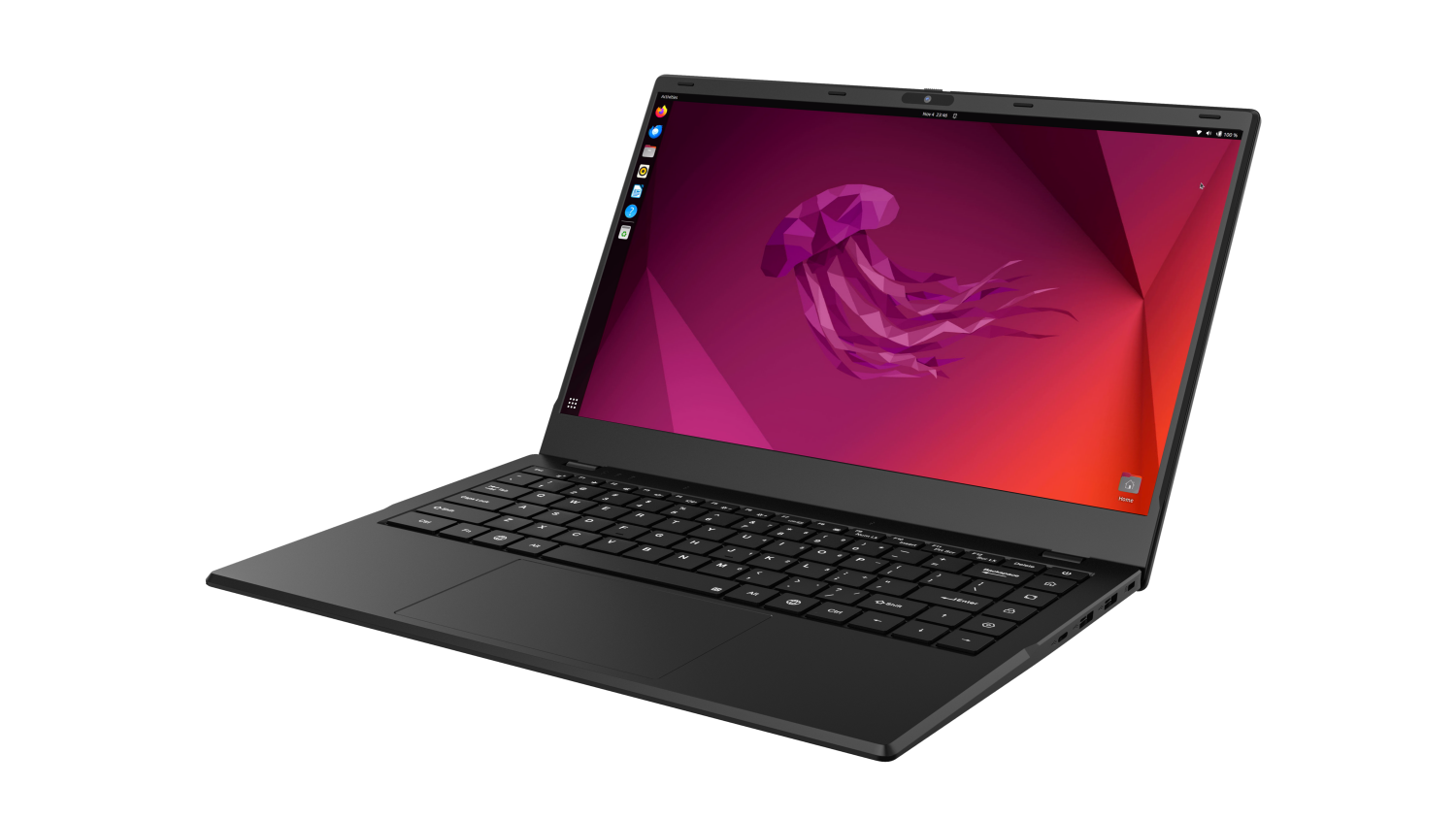
创新无限,引领未来——RK3588开源笔记本震撼登场!posted in PI CM5 Laptop

尊敬的科技达人们,你是否已经厌倦了传统的笔记本电脑?是否渴望拥有一款能够完全按照自己意愿定制的开源笔记本?现在,我们自豪地宣布,基于强大的RK3588芯片,一款创新的开源笔记本正式亮相!
强大性能
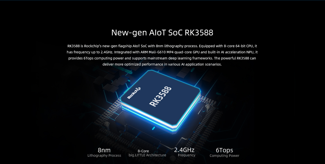
RK3588是瑞芯微电子推出的一款高性能的芯片,定位于高端市场,拥有强大的处理能力和丰富的功能特性。以下是对RK3588芯片的详细介绍:
- 核心架构:RK3588采用了先进的8nm制程工艺,搭载了ARM Cortex-A76和Cortex-A55核心,形成了混合架构设计,既保证了强大的运算性能,又兼顾了能效比。
- GPU性能:RK3588内置了强大的GPU,能够为用户提供流畅的高清视觉体验。这使得RK3588非常适合应用于需要高性能图形处理的场景,如游戏、虚拟现实等。
- AI能力:RK3588集成了高性能的NPU(神经网络处理器),支持AI运算,适用于各种AI应用场景,如图像识别、语音处理等。
- 内存和存储:支持LPDDR4X内存和多种存储接口,包括eMMC、NVMe SSD等,提供快速的数据读写能力。
- 连接性:具备丰富的网络连接功能,包括PCIE网卡、Wi-Fi 6、蓝牙5.0等,满足高速网络需求。
- 多媒体支持:支持多种视频和音频编解码格式,提供高品质的多媒体体验。
- 扩展性:提供多种接口,包括全功能TYPEC、PCIe、HDMI等,支持多种外设和显示设备连接。
- 应用场景:RK3588适用于多种高性能设备,如笔记本电脑、智能电视、家庭娱乐中心、AIoT设备等。
多扩展接口
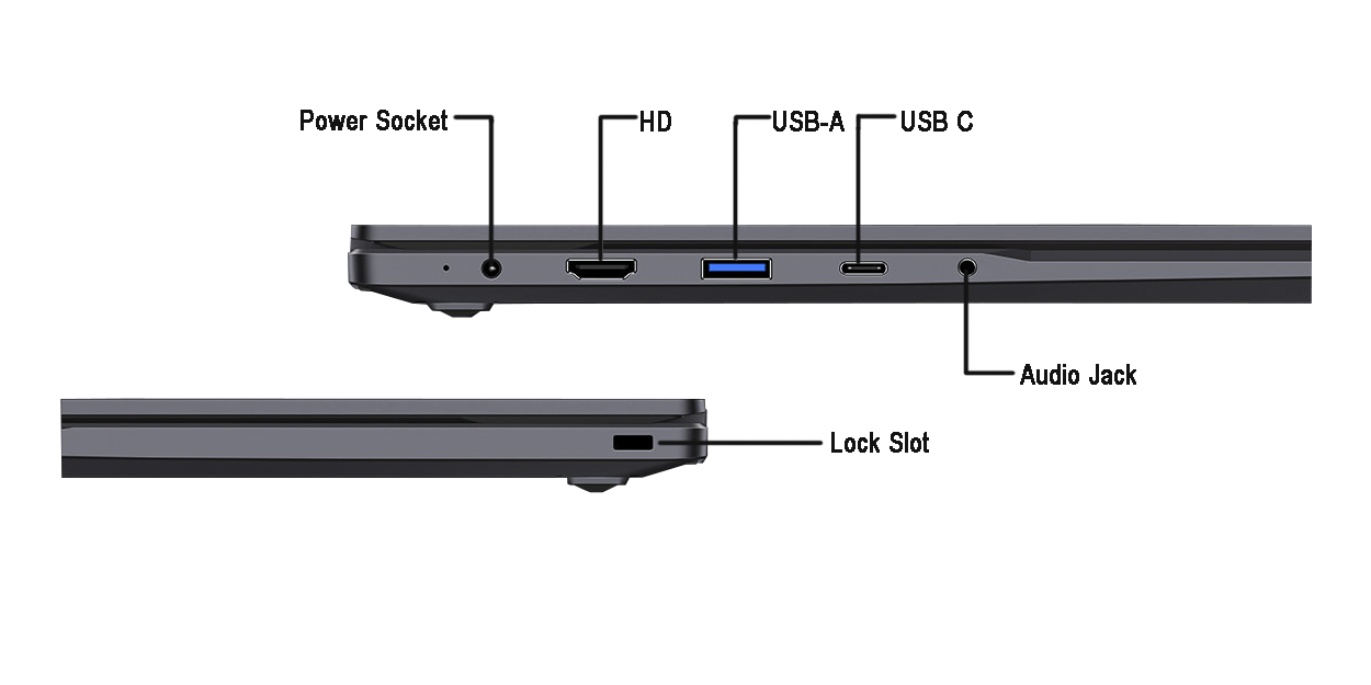
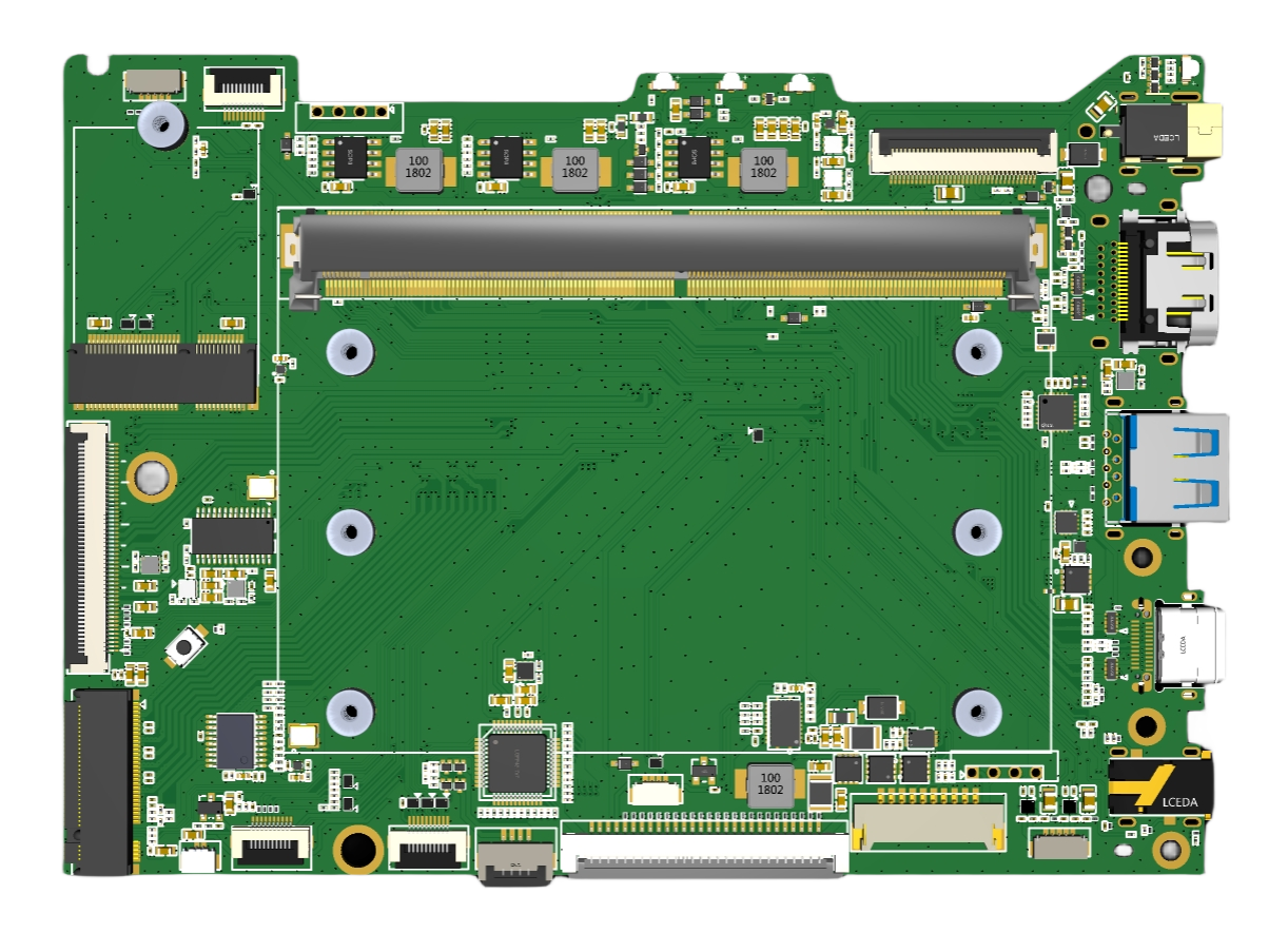
丰富的接口设计,包括PCIE、USB、HDMI、TYPEC等,满足你的各种连接需求,让你无缝连接外部设备。机器主板有丰富的IO扩展功能,如PCIE-M2、USB3.0、USB2.0、SDMMC、I2C、SPI等,方便用户二次开发。
- 外部接口
- 内部接口
开源自由
开源笔记本基于自由开放的软件平台,你可以自由定制操作系统、软件应用,实现个性化定制,发挥你的创造力。
-
WIKI知识库 https://wiki.cool-pi.com/en/home
-
镜像地址 https://pan.baidu.com/s/1CMBGGhGUMMDpg88-WulGWw?pwd=4rjd#list/path=%2F
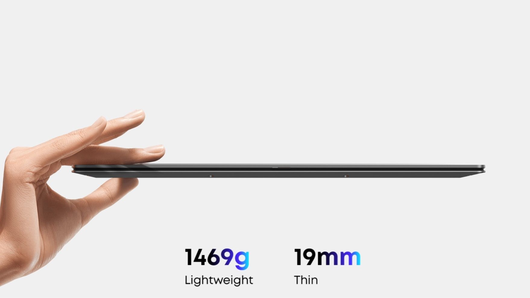
便携设计
轻薄便携的设计,让你随时随地携带,轻松应对移动办公、学习和娱乐的需求。
数据安全
注重用户隐私和数据安全,采用硬件加密技术,确保你的数据安全无忧。
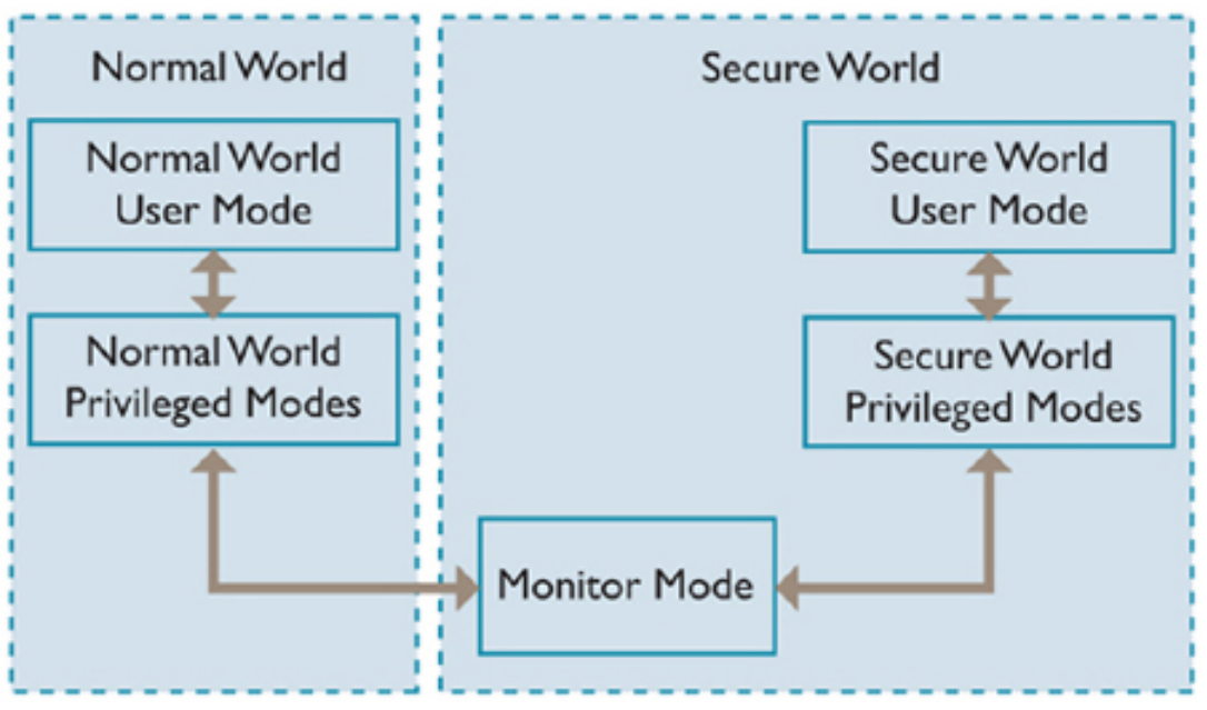
支付、网上银行、内容保护和企业身份验证之类的应用可通过利用TrustZone技术增强型设备所提供的三
个关键要素来提高其完整性、功能和用户体验:- 面向软件的安全执行环境,可防止从富操作系统发起恶意软件攻击
- 已知良好的硬件信任根,可在富操作领域检查数据和应用程序的完整性,确保安全环境不受到损害
- 按需访问安全外设,如内存、键盘/触摸屏,甚至显示器
系统定制
支持多种linux发行版ubuntu、debin、armbian、buildroot、麒麟、统信等,支持安卓系统,支持用户自定义软件界面,支持原生应用开发。提供完善的技术支持。
社区支持
作为开源项目,我们拥有活跃的开发者社区,你可以与其他开发者交流心得,共同学习和进步。
社区地址 https://cool-pi.com/
立即加入我们,一起探索开源笔记本的无限可能!让科技与你同行,共创美好未来!
RK3588开源笔记本,引领科技潮流,打造个性化电脑新体验!
-
Ubuntu23.04 for CoolPiposted in Pi CM5
Default Account
username:coolpi password:123
Update GPU driver
sudo add-apt-repository ppa:george-coolpi/mali-g610
sudo apt-get dist-upgrade
Update multimedia decoding library
sudo add-apt-repository ppa:george-coolpi/multimedia sudo apt-get dist-upgrade -
RE: Heatsync optionsposted in Peripheral
@zensation The radiator can be matched with raspberry pi. A separate fan is OK. Normally, it is not necessary to add aluminum alloy fins on the CPU.
-
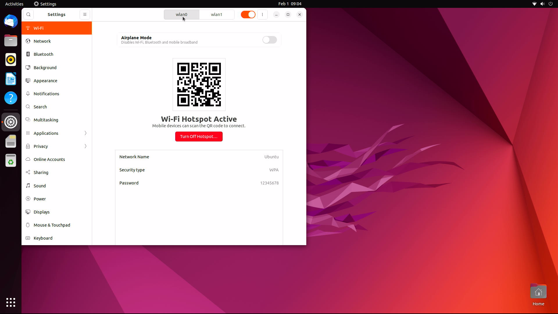
RE: [ ubutnu 22.04 ] AP+STA mode 似乎無法同時啟用?posted in Ubuntu
内核已经更新,同步develop代码到最新,编译替换内核,KO文件解压到/lib/modules目录,重启机器会看到两个WIFI节点。
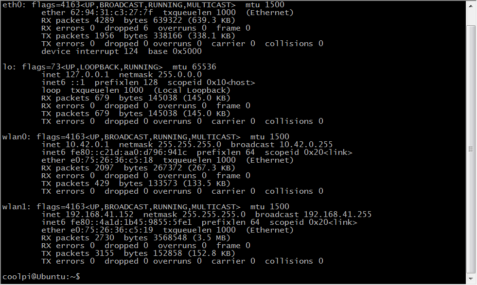
使用其中一个连接外网
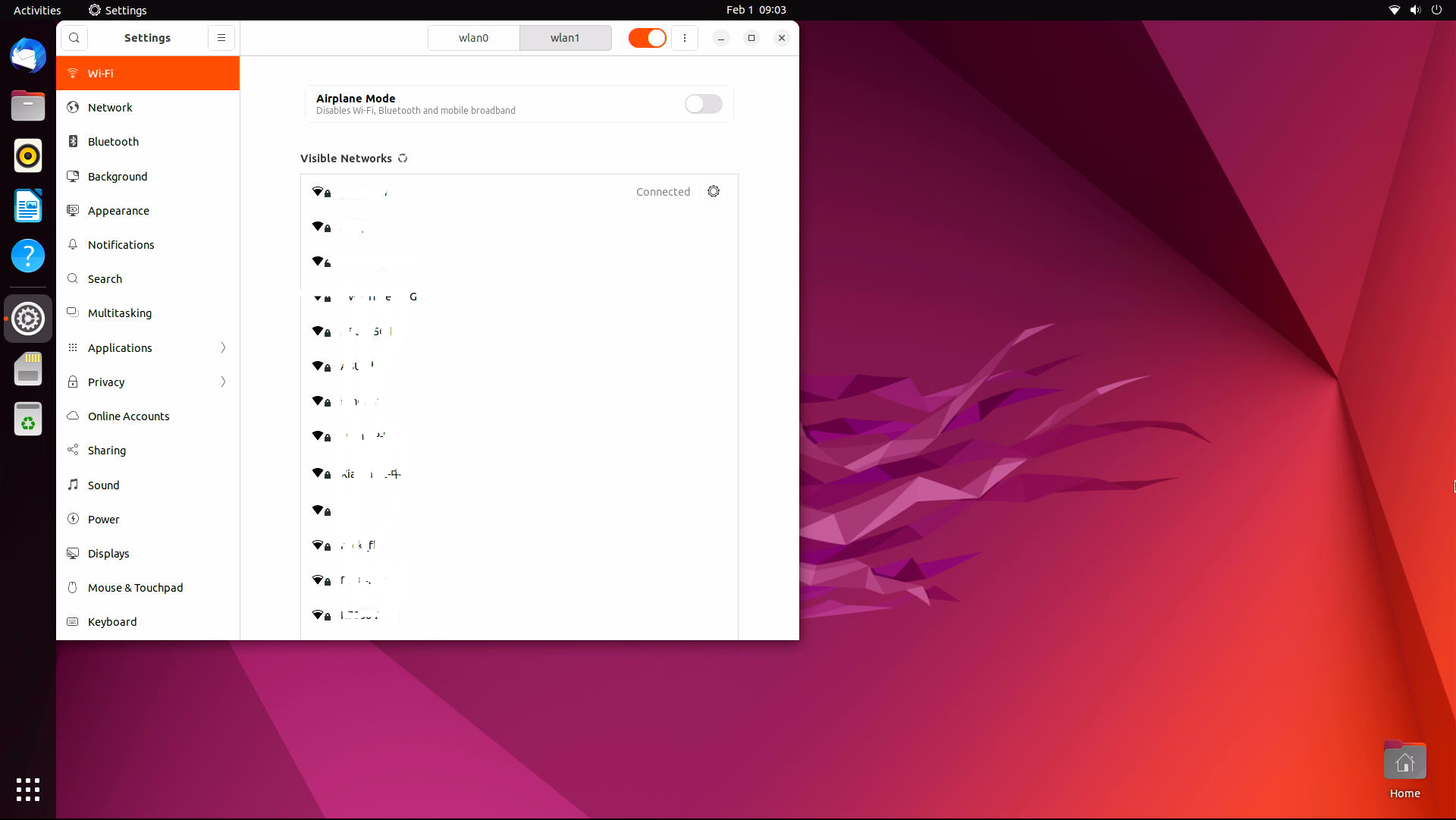
另外一个可以作为热点
-
RE: Booting from USB driveposted in PI CM5 Laptop
@Rock
The current human-computer interaction interface of uboot is not yet perfect. We are trying to do this and will notify you of the version launch as soon as possible. Thank you for your support. -
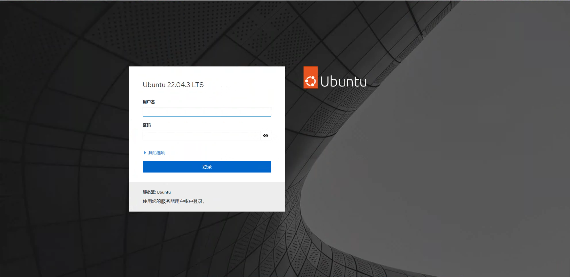
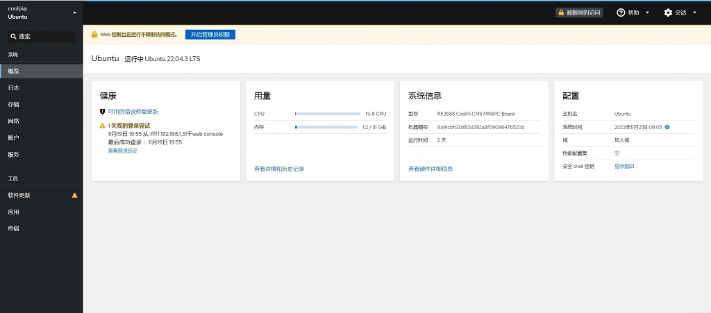
Installing Cockpit on coolpiposted in Pi CM5
- By default, the Cockpit package is included in the Ubuntu 22.04 default repository. You can install it by running the following command:
sudo apt-get install cockpit -y- After installing Cockpit, run the following command to install the Podman module:
sudo apt-get install cockpit-podman -y- After installing Cockpit, start the Cockpit service and have it start when the system reboots:
systemctl start cockpit systemctl enable cockpit- You can also use the following command to check the status of Cockpit:
systemctl status cockpit- You should see the following output:
●cockpit.service - Cockpit Web Service Loaded: loaded (/lib/systemd/system/cockpit.service; static) Active: active (running) since Tue 2023-11-21 08:44:56 UTC; 7min ago TriggeredBy: ● cockpit.socket Docs: man:cockpit-ws(8) Process: 336904 ExecStartPre=/usr/lib/cockpit/cockpit-certificate-ensure --for-cockpit-tls (code=exited, status=0/SUCCESS) Main PID: 336905 (cockpit-tls) Tasks: 3 (limit: 37954) Memory: 1.5M CPU: 358ms CGroup: /system.slice/cockpit.service └─336905 /usr/lib/cockpit/cockpit-tls- At this point, Cockpit has started and is listening on port 9090. You can use the following command to view:
ss -antpl | grep 9090- You should see the following output:
LISTEN 0 0 *:9090 *:*-
Configure a UFW firewall and open port 9090
-
Now, open a web browser and use the URL https://your-server-ip:9090 Access the Cockpit web interface. You should see the Cockpit login page: