@tonyone0902 确认loaer有没有更新到最新,可以按照下图链接更新:https://www.cool-pi.com/topic/162/how-to-upgrade-the-boot-loader-of-coolpi-4b?_=1675398036886
G
Posts made by george
-
RE: 自动连接WIFIposted in Ubuntu
@ccjjww1222 shell输出命令,然后把edid.bin上传:
cat /sys/class/drm/card0-HDMI*/edid > /data/edid.bin -
RE: 是否有 pin22 & pin24 接 Dmic Example?posted in Hardware
- DTS is modified as follows
diff --git a/arch/arm64/boot/dts/rockchip/rk3588s-cp4.dts b/arch/arm64/boot/dts/rockchip/rk3588s-cp4.dts index dc232a407a8c..da9796bfe7a3 100755 --- a/arch/arm64/boot/dts/rockchip/rk3588s-cp4.dts +++ b/arch/arm64/boot/dts/rockchip/rk3588s-cp4.dts @@ -223,6 +223,24 @@ codec { }; }; + pdmics: dummy-codec { + status = "okay"; + compatible = "rockchip,dummy-codec"; + #sound-dai-cells = <0>; + }; + + pdm_mic_array: pdm-mic-array { + status = "okay"; + compatible = "simple-audio-card"; + simple-audio-card,name = "rockchip,pdm-mic-array"; + simple-audio-card,cpu { + sound-dai = <&pdm1>; + }; + simple-audio-card,codec { + sound-dai = <&pdmics>; + }; + }; + leds: leds { compatible = "gpio-leds"; pinctrl-names = "default"; @@ -944,6 +962,14 @@ &route_hdmi0 { status = "okay"; }; +&pdm1 { + status = "okay"; + rockchip,path-map = <0 1 2 3>; + #sound-dai-cells = <0>; + pinctrl-names = "default"; + pinctrl-0 = <&pdm1m1_clk &pdm1m1_sdi1>; +}; + &i2c0 { status = "okay"; pinctrl-names = "default"; @@ -1301,7 +1327,7 @@ ir_key1 { &spi0 { pinctrl-names = "default"; - status = "okay"; + status = "disabled"; max-freq = <48000000>; /* spi internal clk, don't modify */ spi_dev@0 {- Device information
coolpi@Ubuntu:~$ arecord -l **** List of CAPTURE Hardware Devices **** card 2: rockchipes8316c [rockchip,es8316-codec], device 0: fe470000.i2s-ES8316 HiFi es8316.7-0010-0 [fe470000.i2s-ES8316 HiFi es8316.7-0010-0] Subdevices: 1/1 Subdevice #0: subdevice #0 card 3: rockchippdmmica [rockchip,pdm-mic-array], device 0: fe4c0000.pdm-dummy_codec dummy-codec-0 [fe4c0000.pdm-dummy_codec dummy-codec-0] Subdevices: 1/1 Subdevice #0: subdevice #0 -
RE: [ ubutnu 22.04 ] AP+STA mode 似乎無法同時啟用?posted in Ubuntu
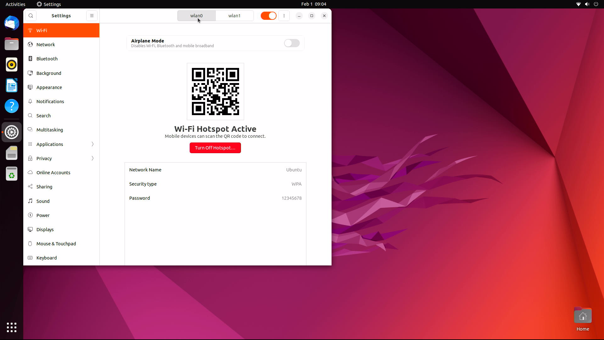
内核已经更新,同步develop代码到最新,编译替换内核,KO文件解压到/lib/modules目录,重启机器会看到两个WIFI节点。
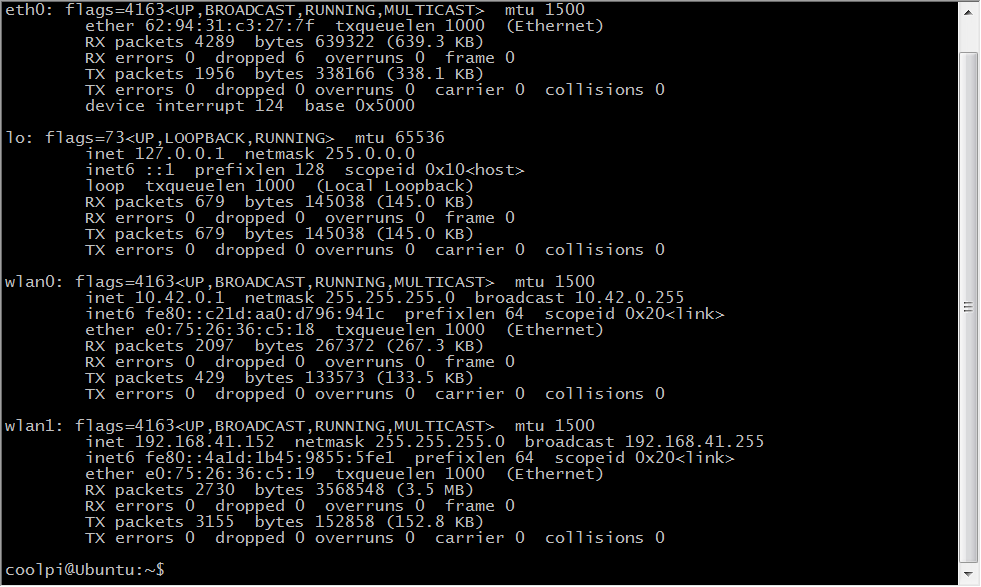
使用其中一个连接外网
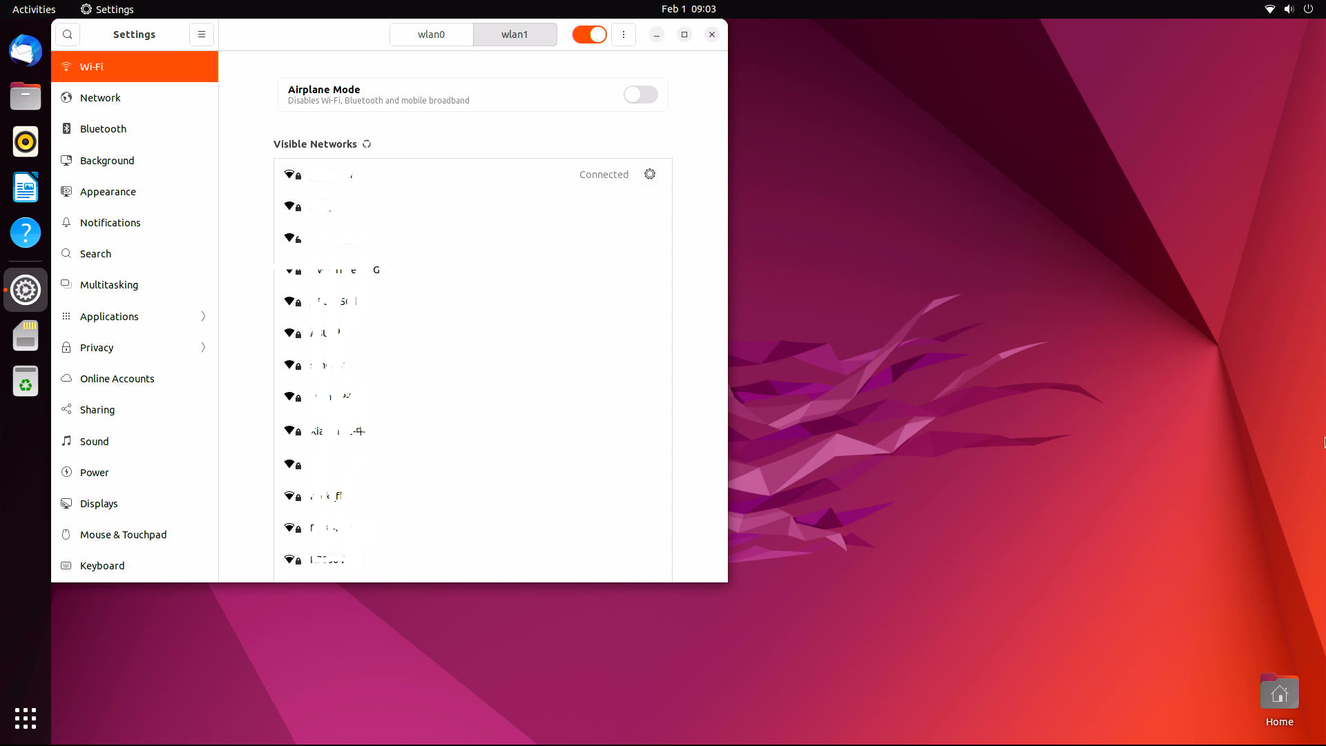
另外一个可以作为热点
-
RE: [ ubutnu 22.04 ] AP+STA mode 似乎無法同時啟用?posted in Ubuntu
@tonyone0902 STA+AP共存驱动部分需要更新。我们尽快处理,请留意内核更新。
-
RE: ubuntu 22.04 chromium-browser 打開後,會直接重新啟動posted in Ubuntu
@tonyone0902 使用支持TYPEC PD或者QC协议的电源适配器,会默认诱导输出12V电压,如果适配器没有12V的档位,会降低到9V。使用普通的5V适配器实际输出就是5V。
-
RE: How to drive a TTL (RGB) interface LCDposted in Hardware
@retroman Has been updated, please check.
-
How to drive a edp interface LCDposted in Hardware
There are many options for LCD with Cool Pi driving edp interface.
- DP directly drives edp
The two protocols are basically the same. At present, only a few edp interface screens can not be lit normally according to the test results.
DP PIN number Signal edp Signal 16 DP_AUXP eDP_AUXP 18 DP_AUXN eDP_AUXN 3 DP_TX0P eDP_TX0P 5 DP_TX0N eDP_TX0N 9 DP_TX1P eDP_TX1P 11 DP_TX1N eDP_TX1N -
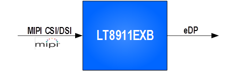
Mipi dsi to edp
Specification LT8911EXB_Datasheet_R1.0.pdf
-
HDMI interface direct drive
The RK3588S HDMI interface can be compatible with HDMI or edp functions. By modifying the DTS configuration, the HDMI interface signal can be directly used as an edp signal. The following figure lists the corresponding relationship between HDMI and edp signals.
HDMI PIN number Signal edp Signal 2 HDMI0_SBDP eDP_AUXP 1 HDMI0_SBDN eDP_AUXN 9 HDMI0_TX0P_PORT eDP_TX0P 11 HDMI0_TX0N_PORT eDP_TX0N 6 HDMI0_TX1P_PORT eDP_TX1P 8 HDMI0_TX1N_PORT eDP_TX1N 3 HDMI0_TX2P_PORT eDP_TX2P 5 HDMI0_TX2N_PORT eDP_TX2N 12 HDMI0_TX3P_PORT eDP_TX3P 14 HDMI0_TX3N_PORT eDP_TX3N - DP directly drives edp
-
How to drive a TTL (RGB) interface LCDposted in Hardware
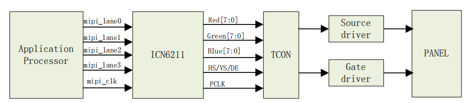
Cool Pi does not have a TTL interface. If you want to drive a TTL interface screen, you need to use a bridge chip. At present, the MIPI to TTL interface chip supports ICN6211 by default. The following details how to use ICN6211 to drive a TTL interface LCD module.
-
Specification
ICN6211_mipi2rgb.brd
MIPI_RGB_162.DSN
ICN6211_MIPI_RGB_specification_V04.pdf -
Block diagram
-
DTS configuration
Enable the following nodes,mipi_dcphy0 dsi0 dsi0_in_vp3 backlight pwm13 .
&mipi_dcphy0 { status = "okay"; }; &dsi0 { status = "okay"; dsi0_panel: panel@0 { status = "okay"; compatible = "simple-panel-dsi"; reg = <0>; backlight = <&backlight>; reset-delay-ms = <60>; enable-delay-ms = <60>; prepare-delay-ms = <60>; unprepare-delay-ms = <60>; disable-delay-ms = <60>; dsi,flags = <(MIPI_DSI_MODE_VIDEO | MIPI_DSI_MODE_VIDEO_BURST | MIPI_DSI_MODE_LPM | MIPI_DSI_MODE_EOT_PACKET)>; dsi,format = <MIPI_DSI_FMT_RGB888>; dsi,lanes = <2>; panel-init-sequence = [ 23 00 02 7A C1 23 00 02 20 20 23 00 02 21 E0 23 00 02 22 13 23 00 02 23 08 23 00 02 24 04 23 00 02 25 08 23 00 02 26 00 23 00 02 27 08 23 00 02 28 04 23 00 02 29 08 23 00 02 34 80 23 00 02 86 29 23 00 02 B5 A0 23 00 02 5C FF 23 00 02 2A 01 23 00 02 56 92 23 00 02 6B 71 23 00 02 69 15 23 00 02 10 40 23 00 02 11 88 23 00 02 B6 20 23 00 02 51 20 23 00 02 09 10 05 78 01 11 05 1E 01 29 ]; panel-exit-sequence = [ 05 00 01 28 05 00 01 10 ]; disp_timings0: display-timings { native-mode = <&dsi0_timing0>; dsi0_timing0: timing0 { clock-frequency = <25000000>; hactive = <800>; vactive = <480>; hfront-porch = <8>; hsync-len = <4>; hback-porch = <8>; vfront-porch = <8>; vsync-len = <4>; vback-porch = <8>; hsync-active = <0>; vsync-active = <0>; de-active = <0>; pixelclk-active = <0>; }; }; ports { #address-cells = <1>; #size-cells = <0>; port@0 { reg = <0>; panel_in_dsi: endpoint { remote-endpoint = <&dsi_out_panel>; }; }; }; }; ports { #address-cells = <1>; #size-cells = <0>; port@1 { reg = <1>; dsi_out_panel: endpoint { remote-endpoint = <&panel_in_dsi>; }; }; }; }; &dsi0_in_vp3 { status = "okay"; }; &backlight { pwms = <&pwm13 0 25000 0>; status = "okay"; }; &pwm13 { status = "okay"; pinctrl-names = "active"; pinctrl-0 = <&pwm13m2_pins>; };- Configure lcdc parameters according to LCD specifications.
LCD specification 5inch DSI LCD (B).pdf
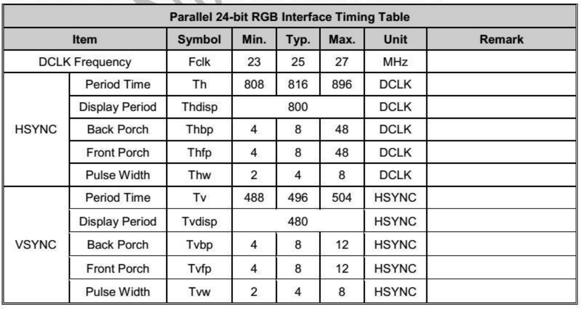
disp_timings0: display-timings { native-mode = <&dsi0_timing0>; dsi0_timing0: timing0 { clock-frequency = <25000000>; hactive = <800>; vactive = <480>; hfront-porch = <8>; hsync-len = <4>; hback-porch = <8>; vfront-porch = <8>; vsync-len = <4>; vback-porch = <8>; hsync-active = <0>; vsync-active = <0>; de-active = <0>; pixelclk-active = <0>; }; };- Generate the initialization sequence of ICN6211 according to the LCD specification.
ICN6211 initialization tool ICN6211 Config.rar
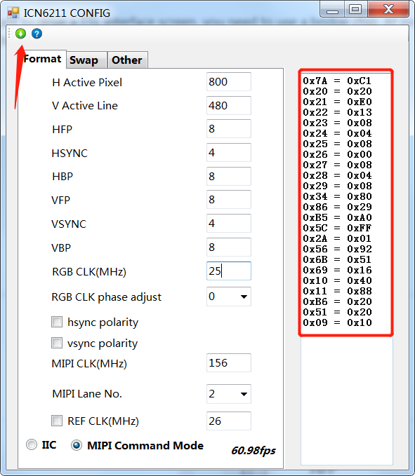
Copy the initialization sequence to DTS according to the command format of rockchip.
Command format description:
23 00 02 7A C1
[Command word] [Delay] [Packet length] [Register] [Value]
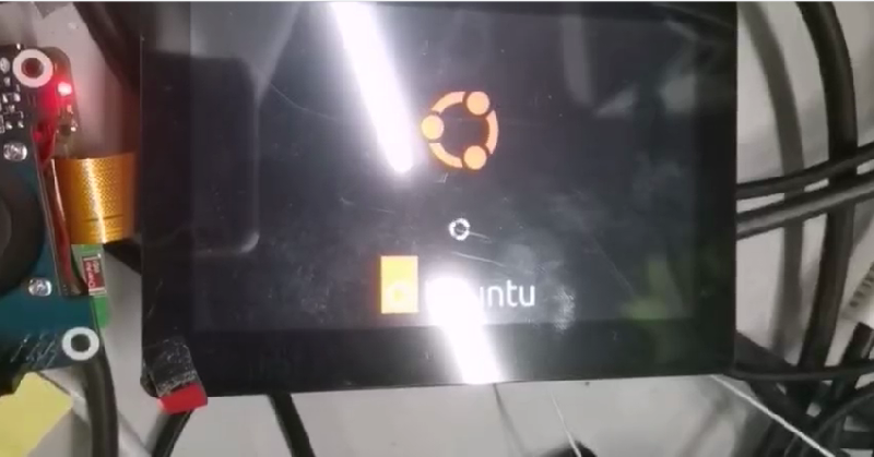
Note that the last 11 29 command is reserved. This is the DSI standard command to open the display.panel-init-sequence = [ 23 00 02 7A C1 23 00 02 20 20 23 00 02 21 E0 23 00 02 22 13 23 00 02 23 08 23 00 02 24 04 23 00 02 25 08 23 00 02 26 00 23 00 02 27 08 23 00 02 28 04 23 00 02 29 08 23 00 02 34 80 23 00 02 86 29 23 00 02 B5 A0 23 00 02 5C FF 23 00 02 2A 01 23 00 02 56 92 23 00 02 6B 71 23 00 02 69 15 23 00 02 10 40 23 00 02 11 88 23 00 02 B6 20 23 00 02 51 20 23 00 02 09 10 05 78 01 11 05 1E 01 29 ];- The TTL signal can be output normally by recompiling and replacing the kernel.
-
-
RE: Coolpi 4B armbian supportposted in Armbian
@retroman The latest firmware is temporarily not compatible with the V10 version of WIFI and BT configurations. This problem will be solved as soon as possible. Please pay attention to the update.
-
RE: 請教如何 grub 更改螢幕解析度?posted in Ubuntu
@tonyone0902 上传图片上来看看,HDMI正常是按照EDID来选择分辨率,手动选择之后是可以保存的。不太清楚画面变胖是什么意思?
-
RE: Coolpi 4B armbian supportposted in Armbian
@retroman said in Coolpi 4B armbian support:
Vulkan
Sorry, Vulkan is not supported for the time being. Please pay attention to the following updates.
-
RE: ubuntu 22.04 chromium-browser 打開後,會直接重新啟動posted in Ubuntu
@tonyone0902 This is usually caused by unstable power supply, such as insufficient input power of the adapter, or power failure at the moment of switching.
-
RE: How to upgrade the boot loader of coolpi 4b?posted in Pi 4B
@reddfoxx Refer to attachment link:
https://www.aliexpress.us/item/3256803830903295.html?spm=a2g0o.productlist.main.51.2d623ca45F44fO&algo_pvid=370776b3-bc3a-44b3-b469-07b7abd5eb71&algo_exp_id=370776b3-bc3a-44b3-b469-07b7abd5eb71-25&pdp_ext_f={"sku_id"%3A"12000027750691599"}&pdp_npi=2%40dis!USD!0.17!0.13!!!!!%40212244c416739165017785791d0685!12000027750691599!sea&curPageLogUid=LiqQEObfPtMi -
RE: Coolpi 4B armbian supportposted in Armbian
@HiramXMaxim Please provide the model of the card reader you use, or take a photo and send it to us. Let's buy the same model and test it. thank you.
-
RE: Coolpi 4B armbian supportposted in Armbian
@HiramXMaxim This may be the compatibility problem of the card reader. You can first make the image into the TF card, and then use the migration script of armbian to migrate the image to EMMC.
-
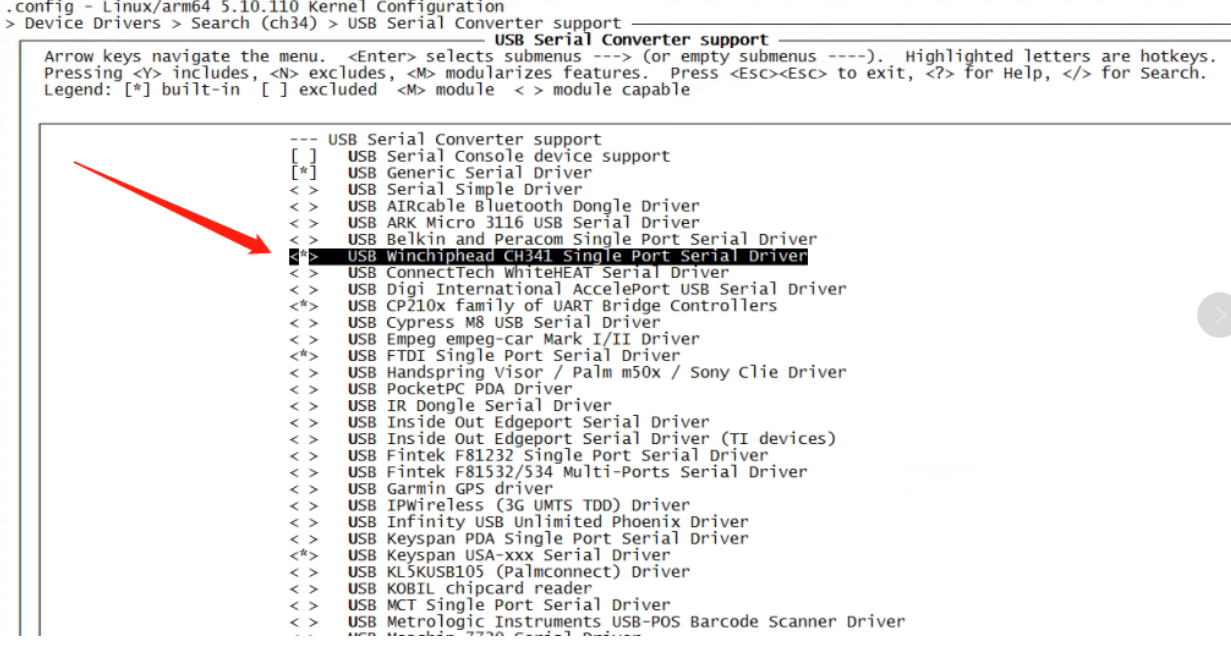
RE: 20221213-ubuntu-20.04-preinstalled-desktop-arm64支持与ch340、ch341等usb转串口芯片通信吗posted in Ubuntu
@bbsvs2000 CH341默认内核config里边没有打开,如下图所示打开配置重新编译内核再测试。
-
RE: Coolpi 4B armbian supportposted in Armbian
@retroman The problem of wifi bt has been solved. Please follow github to submit or download the latest firmware test. Thank you.
-
RE: Coolpi 4B armbian supportposted in Armbian
@retroman The problem of WIFI BT is being solved. An update will be released in the next few days.
-
RE: Coolpi 4B armbian supportposted in Armbian
@retroman Please follow that github will continue to update, thank you.
-
How to upgrade the boot loader of coolpi 4b?posted in Pi 4B
If you need to boot armbian normally, you need to update the loader file to version 0104.
Follow the steps below to update the loader:
-
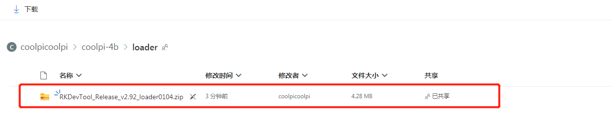
Download the latest loader file One Drive
![5594e1d4-3a7b-46fc-a7b5-2a9fe418dfc0-image.png]
-
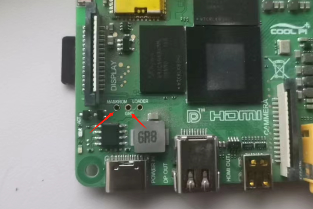
Short the 2 pins shown by the arrow.
-
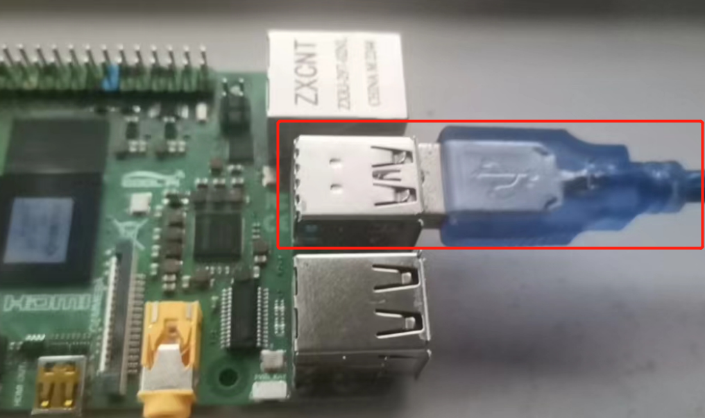
The USB interface and computer connection.
-
Plug in the power supply and open the upgrade software. The machine enters the maskrom upgrade mode.
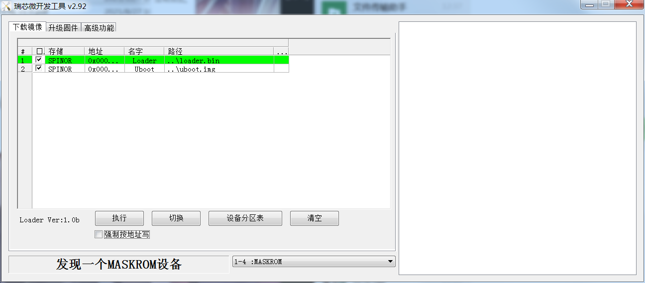
-
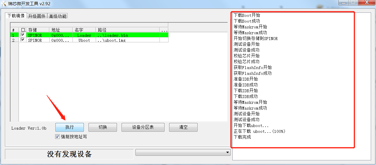
choose to write by address

-
Click Execute to complete the loader update.
-
If the computer prompts that the USB driver cannot be found, please download and install the driver software first.One Drive
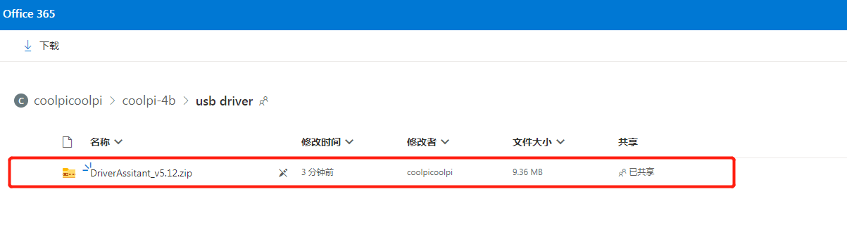
-
-
RE: Coolpi 4B armbian supportposted in Armbian
@retroman Try formatting the TF card before mirroring it. If it does not work properly, it is recommended to upgrade the loader file.
-
RE: Coolpi 4B armbian supportposted in Armbian
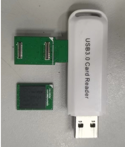
@HiramXMaxim The EMMC small board has an adapter for converting to TF card, which can be written to the EMMC using a common card reader. As shown in the figure below.
-
Coolpi 4B armbian supportposted in Armbian
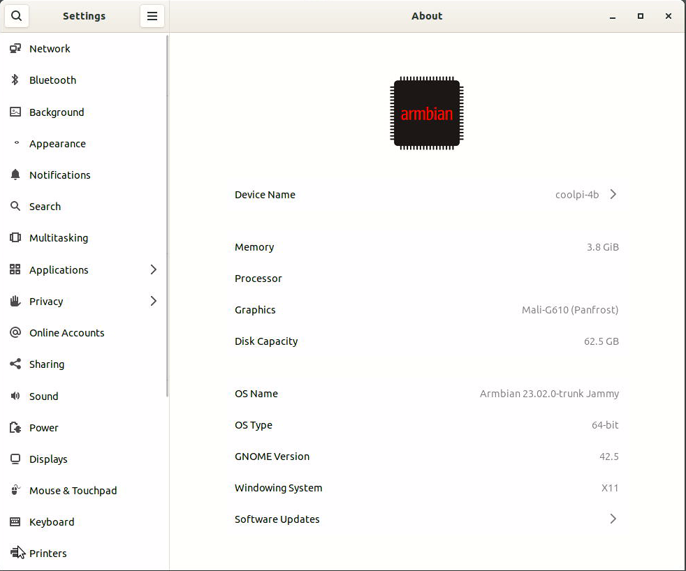
Open source repositories:Github
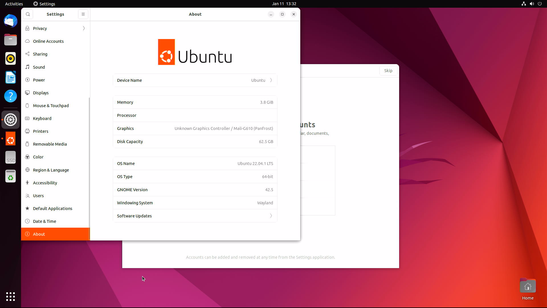
Image download:One Driveenable 3D acceleration:
sudo add-apt-repository ppa:george-coolpi/mali-g610
sudo add-apt-repository ppa:george-coolpi/multimedia
sudo apt update
sudo apt dist-upgrade
installing the MPV video player:(Support rkmpp hardware decoding)
sudo apt-get install mpv -
RE: Would Cool Pi provide Batocera, Retropie, Lakka, Recalbox devs cool pi 4B boards for support?posted in Maker
@retroman Thank you for your suggestion. We will discuss the time point of support internally.